To better understand a filter’s functionality and performance, there are mathematical functions that represent a filter theoretically, such as transfer function, quality factor, and cutoff frequency. Understanding these terms will make it easier to understand a filter property.
Terminologies (definitions)
Transfer function: The inputs and outputs of an op-amp circuit may be voltages, currents, or a combination of the two. When you use complex numbers for the input and output quantities, the ratio of output to input becomes a function of the frequency. The name for the ratio is the transfer function.
Laplace transform: Laplace transform is used to solve differential equations, Laplace transform converts the differential equation into an algebraic problem which is relatively easy to solve.
Time variant system: time delay or time advance in input signal changes not only the output but also the other parameters.
Transfer function
Transfer function is the ratio of the output’s laplace transform to the input’s Laplace transform when all the initial conditions are assumed to be zero. The transfer function can not be defined if the initial condition is not considered to be zero.
Zero initial conditions mean the system should be linear, as linear time-variant systems are used in practice.
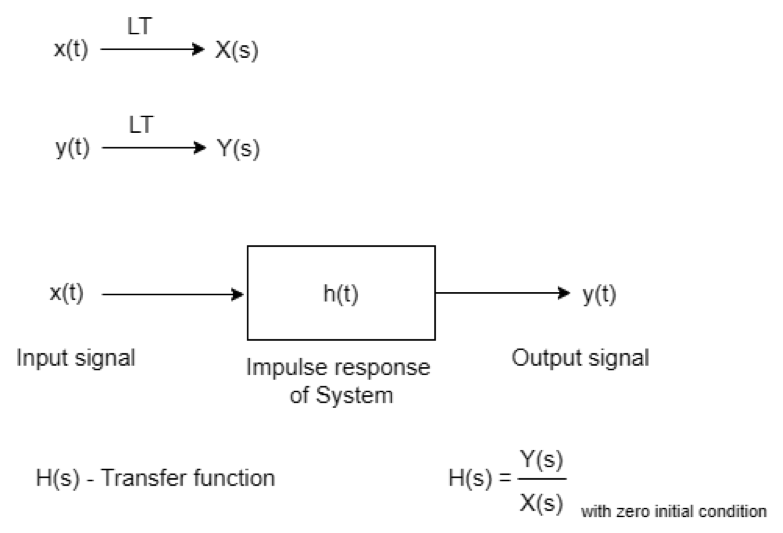
Figure 1 Transfer function block diagram.
Because of the impedance of an inductor or a capacitor, filters have a frequency-dependent response that changes with frequency.
As the time-variant signals are used in practice, and these signals pass through a circuit (Filtration, amplification, attenuation) so there is the possibility that these signals can get affected by the components (Inductor, capacitor, and resistors) used in the circuit. And filters are used to attenuate some part of the signal frequency.
As we know,w the impedances of a capacitor and an induction, respectively are
Zc = 1/sC
Zl = sL
S-Plane s = ó +jù
S-plane is a complex plane (which have real and imaginary components) in mathematics on which Laplace transform can be plotted.
Where ó neper frequency, nepers per second (NP/s)
ù angular frequency (rad/sec)
The filter’s transfer function can be developed using standard circuit analysis techniques. These techniques are Kirchoff’s voltage and current laws, ohm’s law, and superposition. As we know that impedances are complex, then the transfer function will be
H(s) = msm + am-1sm-1 + …+ a1s + a0 bnsn + bn-1sn-1 +…+ b1s + b0
Where m is the degree of the numerator, n is the degree of the denominator, and H(s) is the rational function of s.
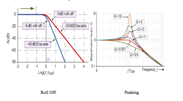
The degree of the denominator is called the order of the filter. By solving the above equation, you will get roots that determine the zeros (numerator) and poles (denominator) of the filter circuit. Each pole provides a -6 dB/octave or -20 dB/decade response and each zeros provides a +6dB/octave or +20 dB/decade response. Calculated roots of the transfer function can be real or complex. If they are complex, then the roots are plotted in the s plane (the complex plane) where the horizontal axis is real (ó,), and the vertical axis is the imaginary axis (ù). The distribution of roots in the s plane or complex plane tells us many things about the filter circuit In order to have stability in the system all poles must lie on the left side of the complex plane. Zero at the origin means there is zero in the numerator, meanings the filter will have no response at dc.
Let’s consider the RLC circuit and write a transfer function for this.
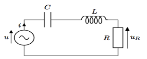
The voltag across the resistor is
H(s) = VoVin = RCsLCs2 + RCs +1)
If R = 10, L =10mH, C=10uF then substituting the components values.
H(s) = 103 x(s2 + 103s + 107)
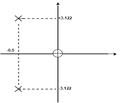
After the factorization,
H(s) = 103 x (s[s-(-0.5+j3.122)x103] x [s-(-0.5-j3.122)x103])
AThe aboveequation gives a zero at othe rigin and pole at:
S = (-0.5±j3.122)x 103
The above s plane shows these points.
In real applications, we are more interested in hardware circuit performance in most cases. But we should also look into the s-plane of the filter, Neper, and imaginary frequencies.
Cutoff frequency (F0) and Quality factor (Q)
Working with an s-plane is not that convenient, then the question arises why? The answer is, it is necessary to know about the transfer function to understand the quality factor and cutoff frequency.
Cutoff frequency (F0)
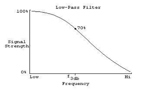
The cutoff frequency is the frequency from where the filter starts filtering the signal, so the cutoff frequency on a low-pass filter is the frequency from where the filter starts removing the high frequencies, the cutoff frequency actually the point where the output level is 3 dB lower than the input level, so it’s not the exactly the point where the filter starts working.
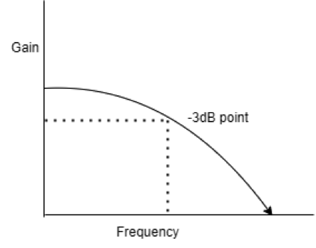
The cutoff frequency is a boundary in a system’s frequency response; energy flowing through the system begins to be reduced, attenuated, or reflected rather than passing through. Typically, in electronics systems such as filters and communication channels, cutoff frequency applies to an edge on low-pass, high pass, bandpass, or band stop characteristics of a frequency characterizing a boundary between the pass band and stop band. It is sometimes taken to the point in the filter response, where the transition band and pass band meet.
Cutoff frequency is defined, in general, as the frequency at which the response of the filter is down 3dB from the pass band. The frequency at which the ratio of (output/input) has a magnitude of 0.707. If you convert this magnitude to decibels it comes -3dB, meaning a 3dB down point.
dB = 20 log (0.707)
The amount of attenuation by the filter begins to increase rapidly at this point as shown in the figure below.
Quality factor (Q)
Quality factor is the measure of the peaking of the filter. Q is really only valid for the second-order filter and not valid for first-order or third-order systems. Quality factor is defined as the potential drop across the inductor or capacitor to the potential drop across the resistor.
Q = (Voltage drop across “L”)/ ( voltage drop across “R”)
Or
Q = (voltage drop across “C”) / (voltage drop across “R”)
Calculation of quality factor for inductor:
Q = (i XL ) / (i R)
Q = XL / R = wL / R
Q = 2pfL / R
f is the resonant frequency, f = 1/2p sqrt(LC)
Q = (1/R) sqrt(L/C)
Similarly, the quality factor for a capacitor is also calculated which is also,
Q = (1/R) sqrt(L/C)
For an RC, LR, or RLC circuit the transfer function will be the same as the above equation.
Quality factor is how under-damped a resonator is, which means how rapidly an oscillation dies out.
Q is the quality factor, and the quality factor transform function is expressed as
α = 1/Q
If Q > 0.707, There will be peaking in the filter response.
If Q < 0.707, roll off at f0 will be greater.
You may also like:

Filed Under: Tech Articles

Questions related to this article?
👉Ask and discuss on Electro-Tech-Online.com and EDAboard.com forums.
Tell Us What You Think!!
You must be logged in to post a comment.