AC to DC conversion is an essential step in power circuit design. Generally step down transformers are used for AC to DC conversion. But the use of a transformer makes the circuit bulky. There is no replacement of transformers when current requirement of the load circuit is high. However when low currents are needed to be drawn by the load circuit, X-rated non-polarity capacitors can also be used for AC to DC conversion. These kind of power supplies are called capacitor power supplies or transformer less power supplies. The transformer less power supply uses Reactance of a capacitor to reduce the voltage. The capacitor which steps down the AC voltage is known as dropping capacitor.
The capacitors used for stepping down the AC voltage are non-polarized X rated capacitors. These X-rated capacitors are designed to pass an AC of high volts according to their voltage rating (e.g. 250V, 400V, 600V). Any normal electrolyte capacitor will not work for the purpose. The electrolyte capacitor has a fixed polarity at its plates. Therefore when AC is applied to its plates, the plates of the capacitor will get two opposite polarity by positive and negative half of the AC. Therefore in any one of the AC cycle, the capacitor plates will get reverse polarity generating holes in the dielectric of the capacitor. So a normal electrolyte capacitor will crack out due to the AC signal on passage through the capacitor. The X-rated non-polarized capacitor can be placed at mains to reduce the 230V AC. These capacitors need to be connected line to line and are built to be used in high voltage AC circuits.
The power supply circuit designed in this project inputs 220-230 V AC from mains and steps it down to 5.67 V DC. The circuit has maximum current limit of 7.2 mA at the output.
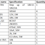
Components Required –
|
Components name |
Specification |
Quantity |
|
Capacitor C1 |
0.1uF, 400V ceramic |
1 |
|
Capacitor C2 |
2200uF 25V |
1 |
|
Capacitor C3 |
0.47uF 25V |
1 |
|
Resistor R1 |
200k 1W |
1 |
|
Resistor R2 |
100 ohm 1W |
1 |
|
Diode D1-D4 |
1N4007 |
4 |
|
Zener diode D5 |
5.6V 500mW |
1 |
Block Diagram –

Fig. 1: Block Diagram of Transformer less AC to DC Power Supply
Circuit Connections –
The phase line of the mains is connected to a ceramic capacitor of 0.1 uF 400V rating and a bleeding resistor (shown as R1 in the schematics) is connected parallel to the capacitor. This RC circuit is connected in series to a full-wave rectifier. The full bridge rectifier is built by connecting four 1N4007 diodes to each other designated as D1, D2, D3 and D4 in the schematics. The cathode of D1 and anode of D2 is connected to phase line via RC circuit and cathode of D4 and anode of D3 is connected to neutral wire. The cathodes of D2 and D3 are connected from which one terminal is taken out for output of rectifier and anodes of D1 and D4 are connected from which other terminal is taken out for output from full-wave rectifier.
A capacitor of 2200 uF is connected across the output terminals of full-bridge rectifier for smoothing of the DC pulse and a zener diode of 5.6V rating is connected at the output terminals of the circuit for voltage regulation.
How the circuit works –
The functioning of the circuit can be break down in following operations –
1. AC to AC Conversion
2. AC to DC Conversion – Full Wave Rectification
3. Smoothing
4. Voltage Regulation
AC to AC Conversion
The voltage of Mains is approximately 220-230V which has to be stepped down to 5.6 V AC before converting to DC at the output. To reduce the 220V AC, an X-rated capacitor of 0.1 uF 400 V rating is used in series with the phase line. The resistor R1 of 200 k ohms and 1 W power rating is connected parallel with the capacitor. The resistor R1 is a bleeder resistor which is used for safety purpose. Bleeder resistor discharges the capacitor when the circuit is unplugged and avoids any electric shock. The voltage drop across the capacitor depends on the load value at the output and on the reactance of the capacitor.
Reactance of the capacitor
X= 1/ (2*π*f*C);
Taking π=3.14
supply frequency of AC (f) = 50 Hz
Capacitance (C) = 0.1 uF
Reactance (X) = 31.8 k ohm
Maximum current provided by the supply is derived as follow –
I(theoretical) = V/X (V = 230V AC)
I(theoretical) = 230/31800
I(theoretical) = 7.2 mA

Fig. 2: Circuit Diagram of AC Voltage Reducer based on X-rated Capacitor and Bleeding Resistor
AC to DC conversion – Full Wave Rectification
The stepped down AC voltage needs to be converted to DC voltage through rectification. The rectification is the process of converting AC voltage to DC voltage. There are two ways to convert an AC signal to the DC one. One is half wave rectification and another is full wave rectification. In this circuit, a full wave bridge rectifier is used for converting the AC voltage to DC voltage. The full wave rectification is more efficient than half wave rectification since it provide complete use of both the negative and positive sides of AC signal. In full wave bridge rectifier configuration, four diodes are connected in such a way that current flows through them in only one direction resulting in a DC signal at the output. During full wave rectification, at a time two diodes become forward biased and another two diodes get reverse biased.

Fig. 3: Circuit Diagram of Full Wave Rectifier
During the positive half cycle of the supply, diodes D2 and D4 conduct in series while diodes D1 and D3 are reverse biased and the current flows through the output terminal passing through D2, output terminal and the D4. During the negative half cycle of the supply, diodes D1 and D3 conduct in series, but diodes D1 and D2 are reverse biased and the current flows through D3, output terminal and the D1. The direction of current both ways through the output terminal in both conditions remain the same.

Fig. 4: Circuit Diagram showing positive cycle of Full Wave Rectifier

Fig. 5: Circuit Diagram showing negative cycle of Full Wave Rectifier
The 1N4007 diodes are chosen to built the full wave rectifier because they have the maximum (average) forward current rating of 1A and in reverse biased condition, they can sustain peak inverse voltage up to 1000V. That is why, 1N4007 diodes are used in this project for full wave rectification.
Smoothing
Smoothing is the process of filtering the DC signal by using a capacitor. The output from the full-wave rectifier is not a steady DC voltage. The output from the rectifier has double the frequency of main supplies but contains ripples. Therefore, it needs to be smoothed by connecting a capacitor in parallel to the output of full wave rectifier. The capacitor charges and discharges during a cycle giving a steady DC voltage as output. So, a capacitor of 2200 uF (shown as C2 in the schematics) is connected to the output of rectifier circuit. As the DC which is to be rectified by the rectifier circuit has many AC spikes and unwanted ripples, so to reduce these spikes capacitor is used. The capacitor acts as a filtering capacitor which bypasses all the AC through it to the ground. At the output, the mean DC voltage left is smoother and ripple free.
The capacitor C2 is of high value and a capacitor C3 of small value is connected parallel to it, so that capacitor C3 decreases the equivalent impedance of the capacitor C2.

Fig. 6: Circuit Diagram of Smoothing Capacitor for Transformer less AC to DC Power Supply
Voltage Regulation
For providing a regulated 5.6 V at the output, a zener diode of 5.6 V 500 mV is connected in series to resistance R2. The diode provides regulated and stabilized voltage at the output irrespective of the fluctuation in the input voltage and variation in the load current. The zener diode provides 7.2 mA current at the output. If a current level other than 7.2 mA is required in the load circuit then capacitor C1 with different value can be replaced with the existing one.
The transformer less supplies can only be used for low current loads. For drawing the current in amperes, a higher value of the X-rated capacitor need to be used so that the impedance of the circuit could be reduced. But during discharging of the capacitor, the current will flow through the bleeder resistor. So a very high watt resistor is required as the bleeder resistor and a resistor having such high watt power rating is not feasible. That is why these type of supplies can be designed only for low current demand circuits.

Fig. 7: Circuit Diagram of Zener Diode based Voltage Regulator
Testing and Precautions –
The following precautions must be taken while assembling the circuit –
For reducing AC voltage level, only a ceramic non- polarized X rated capacitor should be used.
The current rating of a bridge diode must be greater than or equal to the required current at the output. Otherwise, it will be unable to supply the required current at the output.
Always use a capacitor after rectifier circuit so that it can handle mains noise.
The capacitor used in the circuit must be of higher voltage rating than the input supply voltage. Otherwise, the capacitors will start leaking the current due to the excess voltage at their plates and will burst out.
Always use resistor of high watt according to the power dissipation of the circuit.
The power rating of the zener diode must be greater than or equal to the power dissipated by the circuit.
The zener diode starts heating up and get damaged if current flowing across it is greater than its limiting current value (Iz = Pz/Vz = 0.5/5.67 = 88mA).
Once the circuit is assembled, plug it into the mains and use a multimeter to take readings at the output. During testing the voltage across the zener diode was measured 5.67 V and voltage across the resistance R2 was measured 0.69 V. The current through the zener diode and resistance R2 is calculated as follows –
I = V/R2
I = 0.69/100
I = 7mA
The power dissipation across the zener diode is calculated as follows –
P = Vz*I
P = 5.67*0.007
PL = 39mW
The circuit designed in this project can be used to supply power to low current loads and appliances like electronic toys, LED bulbs and electronic gadgets.
You may also like:


Circuit Diagrams
Filed Under: Tutorials

Questions related to this article?
👉Ask and discuss on EDAboard.com and Electro-Tech-Online.com forums.
Tell Us What You Think!!
You must be logged in to post a comment.