In the previous three tutorials of this series, we saw how to vary the intensity (brightness) of LED and DC motor speed using the PWM output of ATtiny85.
In all those previous tutorials, we used only one PWM output, but now we shall simultaneously use three PWM outputs of ATtiny85. ATtiny85 has three PWM outputs on pins 3 (PB4), 5 (PB0), and 6 (PB1). These three PWM outputs vary the intensity of red, green, and blue LEDs of RGB LED. We can generate many different colors from RGB LED by varying the intensity of all three red, green, and blue LEDs. Let’s see how it is done.
If you are not following this tutorial series from the beginning, then you should go through the following two tutorials that explain and demonstrate how to work with ATtiny85 and a step-by-step guide to build a hello world (LED blinking) application.
How to work with ATtiny85
LED blinking using ATtiny85
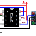
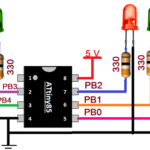
Circuit diagram
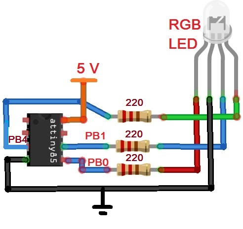
Circuit connections
The circuit is built using only three components RGB LED, 220-ohm resistors, and ATtiny85. RGB LED is used that is of common cathode type. Its red anode is connected with pin PB0 (pin 1), the blue anode is connected with pin PB1 (pin 2), and the green anode is connected with pin PB4 (pin 3). One 220Ω resistor is connected to each anode to limit the current. The cathode of the LED is connected to pin 4 that is connected to ground. A 5 V supply is given to the Vcc pin (8).
Circuit operation
ATtiny85 will generate PWM output on pins PB0, PB1, and PB4. This will vary the intensity of red, blue, and green LEDs. When the intensity of red, green, and blue LED is varied, it will change the proportion of red, green, and blue color from 0 – 100 percent, creating different colors. For example, by applying PWM to red and green LEDs and varying their proportions, we can generate different colors and shades of red, green, yellow, and orange colors.
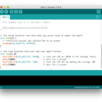
Program
The program is written in Arduino IDE software using the C programming language. It is compiled, and a HEX file is created that is downloaded into the internal FLASH of ATtiny85.
Program logic
The program generates PWM on all three pins PB0, PB1, and PB4.
Firstly, it will turn OFF the green LED by making its intensity 0 and make the red LED fully bright. Then it varies the brightness of the blue LED from minimum to maximum. This will generate different shades and colors of pink and magenta and then change the brightness of red LED from minimum to maximum. Again this will yield different colors and shades of light blue and dark blue colors.
Thus the program will turn ON one LED fully, turn OFF the other LED, and vary the intensity of the third LED. This will generate very nice and eye-catching colors and shades.
The program will start varying the intensity of two colors together like red+green, green+blue, and red+blue. So this will also create so many different colors and shades.
In the next tutorial, we shall learn to interface Bluetooth module HC05 with ATtiny85.
You may also like:
Filed Under: Tutorials

Questions related to this article?
👉Ask and discuss on EDAboard.com and Electro-Tech-Online.com forums.
Tell Us What You Think!!
You must be logged in to post a comment.