In the previous tutorial, a brief introduction of Internet of things was presented. The importance, challenges, applications and trends in IOT were discussed. Now, equipped with basic understanding of IOT, it’s time to investigate the building blocks of IOT. IOT is developed as a package with integration of various technologies. Each technology has its own principle role within the IOT system. In this tutorial, the basic building blocks of IOT and their place in an IOT infrastructure will be examined.
IoT Standards and Protocols: IoT Part 3
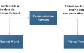
In the previous tutorial, a basic architecture of an IOT system was discussed. From the discussions in the previous tutorial, it must be clear that communication network is the backbone of any IOT system. It is only the (internet) network that enables IOT devices (boards) and cloud based services and applications to communicate with each other. Without internet network, IOT is nothing. Data communication on an internet network is not as straight forward. There are myriad of heterogeneous devices connected over internet and these plethora of unique devices need to communicate in a secure, reliable and routed fashion.
Physical and Data Link Layer Protocols – Ethernet, BLE, Wi-Fi, Wi-Fi Direct and WPA: IoT Part 4
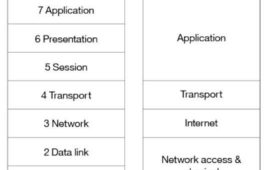
In the previous tutorial, reference architecture for IOT was compared with OSI and TCP-IP models and various data communication protocols for different layers of IOT architecture were mentioned. In this tutorial, the physical and data link layer protocols will be discussed in details. The physical and data link layer comprises of the IOT objects and physical networks connecting them with other objects or network.
Physical and Data Link Layer Protocols for LPWAN: IOT Part 5

In the previous tutorial, various physical and data link layer protocols specified for computers and mobile devices were discussed. Continuing the subject of physical and data link protocols, in this tutorial, network access protocols specified for LPWAN will be discussed. LPWAN stands for Low Power Wide Area Network. In general, LPWAN is a low power long range wireless network in which battery powered IOT devices surrounded by wireless sensors (Wireless Sensor Network) are interconnected.
Physical and Data Link Layer Protocols for LAN, HAN and PAN: IOT Part 6
In the previous tutorial, various physical and data link layer protocols developed for LPWAN were discussed. In this tutorial, protocol stacks developed for Personal Area Network (PAN), Home Area Network (HAN) and Local Area Network (LAN) will be discussed.
Physical and Data Link Layer Protocols – RFID and Mobile Standards: IOT Part 7
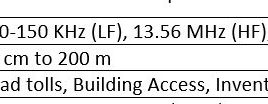
In the previous tutorial, various physical and media access control (MAC) protocol for Personal Area Network (PAN), Home Area Network (HAN) and Local Area Network (LAN) were discussed. In this tutorial, physical and MAC protocols based on RFID and mobile standard will be discussed. There are the following RFID based protocol stacks: RFID, DASH7, NFC.There are the following common mobile standards which are evolving to accommodate IOT applications
What are the programming essentials for LoRa nodes?

LoRa (long-range) technology ensures reliable long-range communication between a node and gateway, making it well-suited for a range of Internet-of-Things (IoT) applications. The purpose of building a LoRa node is to reduce costs while ensuring long-term, low-power use for devices. LoRa’s low power is affected by several features, covered below. Features Smart programming. The written…
Tagore and Inventchip unveil high-efficiency GaN power supply reference design for diverse applications.
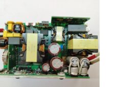
Tagore Technology announced a partnership with Inventchip to introduce a new compact 500 W power supply reference design solution with a Totem Pole PFC front-end and an LLC back-end. Tagore Technology has been delivering disruptive GaN semiconductor solutions for more than 12 years. The reference design uses Tagore’s TP44100SG (90mOhm) and Inventchip’s CCM Totem Pole…
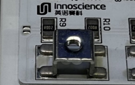
Innoscience introduces 700 V integrated GaN HEMT IC family for USB-PD applications
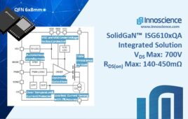
Innoscience announced a family of four new integrated devices that combine power GaN HEMT, driver, current sense, and other functions within a single, industry-standard QFN 6x8mm package. The 700V ISG610x SolidGaN devices cover the range from 140mΩ to 450mΩ and save PCB space and BOM count while increasing efficiency and simplifying design for applications including…
How to control LEDs using the MIT App Inventor and Bluetooth
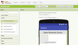
In a previous tutorial, we discussed the MIT App Inventor, a popular online platform for building mobile applications using visual programming. The platform is helpful for quickly prototyping Internet-of-Things (IoT) applications and simple embedded systems that interact with mobile devices. We already reviewed the platform’s architecture and user interface. Its visual programming platform is ideal for…
How to build a facial recognition system using ESP32-CAM
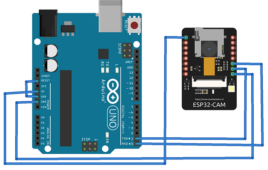
Facial recognition technology identifies individuals by analyzing and comparing their facial features. It uses biometric patterns and algorithms to map and distinguish a person’s unique characteristics. The technology has become an essential component of many security applications. Facial recognition is commonly used for access control, surveillance, biometric authentication, identity verification, criminal identification, attendance, emergency response,…
How to connect Arduino to PC over Ethernet Technology and MQTT Protocol : IOT Part 24
In the previous tutorial, the basics of Ethernet technology were discussed. In this tutorial, the Ethernet technology will be used to connect an Arduino board over internet with a PC. The Arduino based IOT device and the PC will be setup to communicate using MQTT protocol via HiveMQ Broker. An IOT device based on Arduino will be designed in this project. The Arduino will be interfaced with an Arduino Ethernet Shield to connect with a router via Ethernet cable (Cat 5e).
Configuring SIM800 Modem using a PC as server over TCP-IP Protocol: IOT Part 26
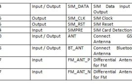
SIM800 is a popular GSM GPRS modem. It supports General Packet Radio Service (GPRS) for connecting to the Internet. This module has built-in TCP/IP stack that can be accessed serially with AT commands.The modem needs to be configured by connecting it to a PC. In such setup, the SIM800 modem with SIM card acts as TCP client and the PC acts as TCP server.
GPRS Technology-General Packet Radio Service : IOT Part 25
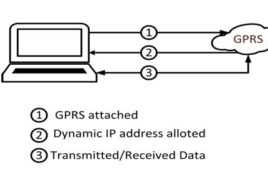
In the previous tutorial, the Ethernet technology was used to connect an Arduino based IOT device with the internet network. The IOT devices can also be connected to internet network using mobile technologies like GSM, CDMA and GPRS. There are two major technologies for data transfers over cellular networks – GSM and GPRS. These two technologies differ from each other on the basis of data rates and the charges they take for their operation.
ESP8266 based IOT Temperature Monitor using Adafruit Broker : IOT Part 21
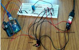
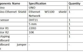
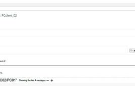
In the previous tutorial, ESP8266 module was used to design a Home Area Network to control an LED light from a remote PC. The PC client was used to send control signals to switch on and off the LED light in the Home Area Network. In this tutorial, the ESP module will be interfaced with DHT-11 temperature sensor and temperature data will be sent to the PC client for real-time temperature monitoring. In this project, instead of LED, the DHT-11 sensor will be interfaced with the ESP8266 on ESP Client side.
Security Enabled M2M Communication using CloudMQTT Broker : IOT Part 19
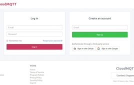
Security is a prime concern in any IoT application development. The data from the IoT devices is passed to the server/cloud where it may be stored temporarily or for long time to generate analytics. The transportation medium through which the data is passed from the IoT device to the cloud must be secured with implementation of various IoT security measures, so that the data could not be hacked by any Man-in-the-Middle attack.
How to Communicate between PC and Mobile using MQTT Protocol Via HiveMQ Broker : IOT Part 18
In the previous tutorial, it was learnt that how a smart phone and a PC can be set up as MQTT clients and their connection with an MQTT broker can be established. The smart phone was configured as an MQTT client using an android MQTT app – IOT MQTT Dashboard while the PC was configured as MQTT client using a chrome add-on – MQTTLens.Now, in this tutorial, these MQTT clients – Mobile and PC will be made to communicate with each other using MQTT protocol. The communication between the MQTT clients is only possible via MQTT broker.
How to build a LoRa gateway using Raspberry Pi
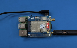
As its name suggests, long-range wide-area network or LoRaWAN technology is widely used for long-range, low-power communication in Internet-of-things (IoT) applications. In this article, we’ll guide you through the process of connecting an SX130x 868M LoRaWAN Gateway Module to a Raspberry Pi 4 using hardware attached on top (HAT). This setup creates a LoRaWAN gateway,…
Innoscience launches 100 V GaN IC for 48V/60V battery management systems
Innoscience Technology has launched a new 100V bi-directional member of the company’s VGaN IC family. The first family of VGaN devices rated 40V with a wide on-resistance range (1.2mOhm – 12mOhm) have been successfully deployed in the USB OVP of mobile phones such as OPPO, OnePlus, etc. The new 100V VGaN (INV100FQ030A) can be employed…
What temperature sensors are used for electronics and IoT devices?
Temperature sensors are commonly used in embedded applications to monitor ambient temperature and prevent overheating. As a thermal management of the device, these sensors can issue a warning or trigger a cooling mechanism. However, the use of these sensors varies, depending on the application. For example, temperature sensors are used in: Industrial equipment for process…