EEPROM with NRF24LE1
All the good and bad incidents are stored in the brain memory of humans. Similarly, the controller uses EEPROM to save data or variables. In this article, we will see how to use the EEPROM of NRF24LE1 and what are its uses?
Do you know what makes the memory in electronics? Let’s take an example of a capacitor. It has the capability to hold voltage and thus it’s treated as memory component. There are two types of memories in electronics; Volatile and non-volatile. The volatile one gets erased if the power supplied to this memory is cut. That means the data stored will be erased in case of power failure. The non-volatile has an advantage of holding data even when the power is off. The most common example of volatile memory is the RAM used in our computers. The examples of volatile memory are hard disk, SD cards, EEPROM, etc.

Fig. 1: Prototype of NRF24LE1 and EEPROM Interfacing
In this article, we will focus on EEPROM in our NRF module and its use. EEPROM stands for Electrically Erasable Programmable Read Only Memory. It is a type of Non-Volatile. It can be programmed and erased by providing special programming signals. They are available in small sizes and can be easily interfaced with AVR, Arduino or PIC. Sometimes they are inbuilt in microcontrollers. But for expansion of memory we have to use the external one.
The NRF24LE1, being an amazing component, has inbuilt EEPROM memory. It has 1.5 Kb of Non Volatile data memory. This memory proves useful when we interface sensors and want to retain the readings for future use. For using read and write features of this memory we will use function in our code.
We will use nrfsdk (software development kit) provided by Nordic Semiconductor Ltd.
Please visit our previous article on NRF24LE1 for more help.
Some functions we will be using to read and write EEPROM are:
• lib_eeprom_byte_write() – This function takes address location and a byte data to be written.
• lib_eeprom_bytes_write() – This function take multiple bytes of data along with the number of bytes and starting address.
• lib_eeprom_byte_read() – This function outputs a byte data from the provided memory address.
| FUNCTION | INPUT PARAMETER | OUTPUT | DESCRIPTION |
|---|---|---|---|
| lib_eeprom_byte_write() | 8-bit address and 8-bit data | – | To write 8-bit data to specified –bit address |
| lib_eeprom_bytes_write() | 8-bit address, 8-bit pointer to bytes to write and 8-bit value indicating number of bytes to write | – | To write multiple bytes to specified starting address |
| lib_eeprom_byte_read() | 8-bit address | 8-bit data | To read 8-bit data from specified 8-bit address |
| lib_eeprom_bytes_read() | 8-bit address, 8-bit pointer to bytes to write and 8-bit value indicating number of bytes to read | – | To read multiple bytes from specified starting address. |
For complete understating, please take a look at the implementation of these functions in the code. The code has been commented for greater understanding.
We will write some data to EEPROM memory and then we will restart our system. After that we will read the previously stored data to check the working of the EEPROM.
Project Source Code
###
//Program to/* Copyright (c) 2009 Nordic Semiconductor. All Rights Reserved.
** The information contained herein is confidential property of Nordic* Semiconductor ASA.Terms and conditions of usage are described in detail* in NORDIC SEMICONDUCTOR STANDARD SOFTWARE LICENSE AGREEMENT.** Licensees are granted free, non-transferable use of the information. NO* WARRENTY of ANY KIND is provided. This heading must NOT be removed from* the file.** $LastChangedRevision: 133 $*/#include "reg24le1.h" // I/O header file for NRF24LE1#include "lib_eeprom.h" // header file containing eeprom read/write functions#include "hal_delay.h" // header file containing delay functions// main codevoid main(){P1DIR = 0; // set Port1 as outputP1 = 0; // make all pins of Port1 lowP1 = lib_eeprom_byte_read(0x00); // load 8-bit data from eeprom at address 0x00delay_ms(2000); // delay of 2 secondswhile(1) // infinite loop{P10 = 0; // make pin0 of port1 lowP11 = 0; // make pin1 of port1 lowlib_eeprom_byte_write(0x00, P1); // write P1 register data to eepromdelay_ms(2000); // delay of 2 secondslib_eeprom_byte_write(0x00, P1); // write P1 register data to eepromP10 = 1; // make pin0 of port1 highP11 = 0; // make pin1 of port1 lowlib_eeprom_byte_write(0x00, P1); // write P1 register data to eepromdelay_ms(2000); // delay of 2 secondsP10 = 0; // make pin0 of port1 lowP11 = 1; // make pin1 of port1 highlib_eeprom_byte_write(0x00, P1); // write P1 register data to eepromdelay_ms(2000); // delay of 2 secondsP10 = 1; // make pin0 of port1 highP11 = 1; // make pin1 of port1 highlib_eeprom_byte_write(0x00, P1); // write P1 register data to eepromdelay_ms(2000); // delay of 2 seconds}}###
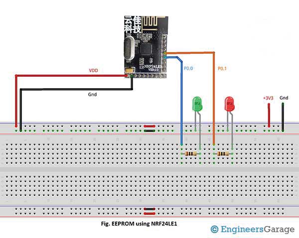
Circuit Diagrams
Project Video
Filed Under: Tutorials
Filed Under: Tutorials

Questions related to this article?
👉Ask and discuss on EDAboard.com and Electro-Tech-Online.com forums.
Tell Us What You Think!!
You must be logged in to post a comment.