What if you could control your robot wirelessly without making a remote or even buying one? Your TV remote which sits in your hands most of the time could do all controlling. Doesn’t that sound good? Well, it is quite easy to implement. Presented here is a Robot based on Arduino that can be controlled by a TV (or any IR Remote). so reader should have knowledge about start with arduino.

Fig. 1: Prototype of TV Remote Controlled Arduino Robot
Basically, the remote controls of electronic appliances be it TV, DVD, etc., work on IR communication principles. They transmit a code, in the form of IR pulses which is decoded by the receiver to carry out a specific operation. Each key is assigned a specific code based on a certain standard protocol developed by the manufacturer.

Fig. 2: Image showing Arduino Circuit on TV Remote Controlled Robot

Fig. 3: Image showing chassis and wheels of TV Remote Controlled Arduino Robot
For the robot to detect commands of the remote, we need to decode the remote and place its commands in the Robot Controller (Arduino). This is done with the help of IR receiver, TSOP1738.
TSOP 1738
The TSOP is a miniaturized receiver for infrared remote control systems. PIN diode and preamplifier are assembled on lead frame, the epoxy package is designed as IR filter. The demodulated output signal can directly be decoded by a microprocessor. TSOP is the standard IR remote control receiver series, supporting all major transmission codes. Its output is Active Low.

Fig. 4: Pin Diagram of TSOP1738 IR Receiver

Fig. 5: Screenshot of Arduino Code used for receiving IR signal by Robot
Making the Robot

Fig. 6: Overview of TV Remote controlled Arduino Robot
Assembly of the robot is shown below:

Fig. 7: Representational Image of mechanical design of Robot
Circuit Diagram (Decoding the Remote)

Fig. 8: Circuit Diagram of Arduino based IR Remote Receiver
Project Source Code
###


#include <IRremote.h>
int RECV_PIN = 11;          // Output pin of TSOP sensor
IRrecv irrecv(RECV_PIN);
decode_results results;
void setup()
{
  pinMode(7,OUTPUT);
  pinMode(8,OUTPUT);
  pinMode(12,OUTPUT);
  pinMode(13,OUTPUT);
  irrecv.enableIRIn(); // Start the receiver
}
void loop()
{
   if (irrecv.decode(&results))
  {
   if((results.value)==0x1CE358A7)
     {
      stp();
     }
   if ((results.value)==0x1CE330CF)
       {
       fwd();
       }
  if ((results.value)==0x1CE3B04F)
       {
       back();
       }
  if ((results.value)==0x1CE3E817)
       {
       left();
        }
  if ((results.value)==0x1CE36897)
       {
       right();
       }
irrecv.resume();           // Receive the next value
}
}
void fwd()          // function to move forward
{
  digitalWrite(7,HIGH);
  digitalWrite(13,HIGH);
  digitalWrite(8,LOW);
  digitalWrite(12,LOW);
}
void back()        // function to move backward
{
  digitalWrite(8,HIGH);
  digitalWrite(13,HIGH);
  digitalWrite(7,LOW);
  digitalWrite(13,LOW);
}
void left()        // function to turn left
{
  digitalWrite(7,HIGH);
  digitalWrite(13,LOW);
  digitalWrite(8,LOW);
  digitalWrite(12,LOW);
}
void right()        // function to turn right
{
  digitalWrite(7,LOW);
  digitalWrite(13,HIGH);
  digitalWrite(8,LOW);
  digitalWrite(12,LOW);
}
void stp()        // function to stop
{
  digitalWrite(7,LOW);
  digitalWrite(13,LOW);
  digitalWrite(8,LOW);
  digitalWrite(12,LOW);
}

###
Circuit Diagrams
| Circuit-Diagram-Motor-Driver-Tv-Remote-Controlled-Robot | 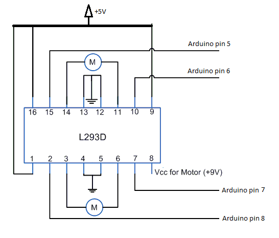 |
| Circuit-Diagram-Arduino-Circuit-Tv-Remote-Controlled-Robot | 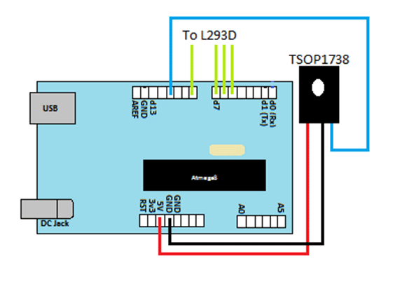 |
Project Video
Filed Under: Electronic Projects
Filed Under: Electronic Projects

Questions related to this article?
👉Ask and discuss on EDAboard.com and Electro-Tech-Online.com forums.
Tell Us What You Think!!
You must be logged in to post a comment.