Engineers Garage

  • Projects and Tutorials
    • Electronic Projects
      • 8051
      • Arduino
      • ARM
      • AVR
      • PIC
      • Raspberry pi
      • STM32
    • Tutorials
    • Circuit Design
    • Project Videos
    • Components
  • Articles
    • Tech Articles
    • Insight
    • Invention Stories
    • How to
    • What Is
  • News
    • Electronic Products News
    • DIY Reviews
    • Guest Post
  • Forums
    • EDABoard.com
    • Electro-Tech-Online
    • EG Forum Archive
  • Digi-Key Store
    • Cables, Wires
    • Connectors, Interconnect
    • Discrete
    • Electromechanical
    • Embedded Computers
    • Enclosures, Hardware, Office
    • Integrated Circuits (ICs)
    • Isolators
    • LED/Optoelectronics
    • Passive
    • Power, Circuit Protection
    • Programmers
    • RF, Wireless
    • Semiconductors
    • Sensors, Transducers
    • Test Products
    • Tools
  • EE Resources
    • DesignFast
    • LEAP Awards
    • Oscilloscope Product Finder
    • White Papers
    • Webinars
  • EE Learning Center
    • Design Guides
      • WiFi & the IOT Design Guide
      • Microcontrollers Design Guide
      • State of the Art Inductors Design Guide
  • Women in Engineering

Two Door Door Bell With Visual Indicator

By Anjali Sethiya


The doorbells produce a ringing alert sound so that the resident comes to know that there is somebody at the door. Many homes have two doors for entering. So, sometime it become confusing for the resident to find out on which door visitor is  present. This project on doorbell circuit produces two different sounds and can be used simultaneously on both the doors. This circuit also gives a visual indicator so that deaf person can also know. For this we use different color LED for different door so that it becomes easy to know whether the visitor is present on front door or rear door.

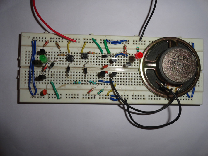
This simple circuit is based on transistor, diode, resistor and switches with few more components.

1. Resistor– Resistor is a two terminal passive component used to control the flow of current into the circuit. A current through resistor is directly proportional to the voltage applied across resistor terminal.

Resistor comes in two varieties – 

1. Fixed resistor means they have fixed value of resistance.

2. Variable resistors means there value can be changed like if you have variable resistor of 5K then you can vary the resistance from 0 to 5 K Ohms.

We can calculate the value of resistor with the help of multi-meter or we can do it with help of color code available on resistor.

2. Diodes– Diode is a two terminal device with a asymmetric characteristic means it allows low resistance to current flow in one direction and high resistance in another direction. Therefore it allows current to flow in one direction and blocks the current that flows in opposite direction. The two terminal of the diode is referred to as anode and cathode. Because of its unidirectional behavior they are used to convert alternating current to direct current.

3. Transistor– Transistor is a three terminal electronic device used to amplify weak input signals. A transistor consists of two PN junction diode connected back to back. Transistors are of different types such as bipolar junction transistor, Field effect transistor and photo transistor. They are mostly used in electrical appliances due their smaller size and light weight. In addition they posses less power hence have greater efficiency.

4. Speaker- Speaker is a transducer which produces sound in response to electrical audio signal applied at input.

5. Capacitor– A capacitor is a two terminal passive component which stores electric charge. Capacitor consists of two conductors which are separated by a dielectric medium. It works when potential difference applied across the conductors polarizes the dipole ions to store the charge in the dielectric medium. Capacitor comes in two varieties-

1. Polarized capacitor- They have polarity means + and – sign. They are basically used to store charge. As they store charge they should be carefully discharge before troubleshooting the circuit.

2. Non polarized capacitor – They does not have polarity and can be mounted any way. They are basically used to remove the fluctuation present in conversion of AC to DC.

Working of circuit

In the circuit given below two switches S1 and S2 are used for front and rear door. When S1 is pressed diode D1 connected to it starts conducting because of that transistor T1 and T2 connected through resistor start conducting. Capacitor C1 is used to provide positive feedback to transistor T1 and T2 for oscillation. When S1 is pressed low frequency tone is generated indicating that visitor is calling from front door.When S1 is pressed at the same time diode D3 also start conducting and this in turn trigger the base of transistor T4. Now this will trigger the transistor T6 and LED 2 connected to start glowing indicating that visitor is present outside. Hence when you press the switch S1, simultaneously speaker will start sounding and LED glows it will glow until switch is released.

Similar kind of phenomenon happens when you press the switch S2. Diode D2 connected to it start conducting which provide power supply to the working of transistor T1 and T2 and the speaker connected to it start sounding. But this time it produces a high frequency tone indicating that visitor is present on rear door. When S2 is press power supply is also provided to diode D4 which also start conducting and because of that transistor T3 and T5 start conduction and LED1 glows to indicate that visitor is present on rear door.


Circuit Diagrams

2-Door-bell-with-visual-indicator.


Filed Under: Electronic Projects
Tagged With: door bell, visual indicator
 

Questions related to this article?
👉Ask and discuss on Electro-Tech-Online.com and EDAboard.com forums.


Tell Us What You Think!! Cancel reply

You must be logged in to post a comment.

HAVE A QUESTION?

Have a technical question about an article or other engineering questions? Check out our engineering forums EDABoard.com and Electro-Tech-Online.com where you can get those questions asked and answered by your peers!


Featured Tutorials

  • Introduction to Brain Waves & its Types (Part 1/13)
  • Understanding NeuroSky EEG Chip in Detail (Part 2/13)
  • Performing Experiments with Brainwaves (Part 3/13)
  • Amplification of EEG Signal and Interfacing with Arduino (Part 4/13)
  • Controlling Led brightness using Meditation and attention level (Part 5/13)
  • Control Motor’s Speed using Meditation and Attention Level of Brain (Part 6/13)

Stay Up To Date

Newsletter Signup

Sign up and receive our weekly newsletter for latest Tech articles, Electronics Projects, Tutorial series and other insightful tech content.

EE Training Center Classrooms

EE Classrooms

Recent Articles

  • What are the battery-selection criteria for low-power design?
  • Key factors to optimize power consumption in an embedded device
  • EdgeLock A5000 Secure Authenticator
  • How to interface a DS18B20 temperature sensor with MicroPython’s Onewire driver
  • Introduction to Brain Waves & its Types (Part 1/13)

Most Popular

5G 555 timer circuit 8051 ai Arduino atmega16 automotive avr bluetooth dc motor display Electronic Part Electronic Parts Fujitsu ic infineontechnologies integratedcircuit Intel IoT ir lcd led maximintegratedproducts microchip microchiptechnology Microchip Technology microcontroller microcontrollers mosfet motor powermanagement Raspberry Pi remote renesaselectronics renesaselectronicscorporation Research samsung semiconductor sensor software STMicroelectronics switch Technology vishayintertechnology wireless

RSS EDABOARD.com Discussions

  • Slope compensation ramp calculation for UCC38084
  • Parts storage / inventory best practices and organization
  • Unusual gap shape of ETD59 ferrite core?
  • Vco cadencd
  • WH-LTE-7S1 GSM module and SIM card problem

RSS Electro-Tech-Online.com Discussions

  • HV Diodes
  • intro to PI
  • Very logical explanation on low calue C3
  • Need help working with or replacing a ferrite tube
  • Help wanted to power an AC120v induction motor ( edited from Brushless motor - thank you @SHORTBUS= )
Engineers Garage
  • Analog IC TIps
  • Connector Tips
  • DesignFast
  • EDABoard Forums
  • EE World Online
  • Electro-Tech-Online Forums
  • Microcontroller Tips
  • Power Electronic Tips
  • Sensor Tips
  • Test and Measurement Tips
  • 5G Technology World
  • About Us
  • Contact Us
  • Advertise

Copyright © 2022 WTWH Media LLC. All Rights Reserved. The material on this site may not be reproduced, distributed, transmitted, cached or otherwise used, except with the prior written permission of WTWH Media
Privacy Policy | Advertising | About Us

Search Engineers Garage

  • Projects and Tutorials
    • Electronic Projects
      • 8051
      • Arduino
      • ARM
      • AVR
      • PIC
      • Raspberry pi
      • STM32
    • Tutorials
    • Circuit Design
    • Project Videos
    • Components
  • Articles
    • Tech Articles
    • Insight
    • Invention Stories
    • How to
    • What Is
  • News
    • Electronic Products News
    • DIY Reviews
    • Guest Post
  • Forums
    • EDABoard.com
    • Electro-Tech-Online
    • EG Forum Archive
  • Digi-Key Store
    • Cables, Wires
    • Connectors, Interconnect
    • Discrete
    • Electromechanical
    • Embedded Computers
    • Enclosures, Hardware, Office
    • Integrated Circuits (ICs)
    • Isolators
    • LED/Optoelectronics
    • Passive
    • Power, Circuit Protection
    • Programmers
    • RF, Wireless
    • Semiconductors
    • Sensors, Transducers
    • Test Products
    • Tools
  • EE Resources
    • DesignFast
    • LEAP Awards
    • Oscilloscope Product Finder
    • White Papers
    • Webinars
  • EE Learning Center
    • Design Guides
      • WiFi & the IOT Design Guide
      • Microcontrollers Design Guide
      • State of the Art Inductors Design Guide
  • Women in Engineering