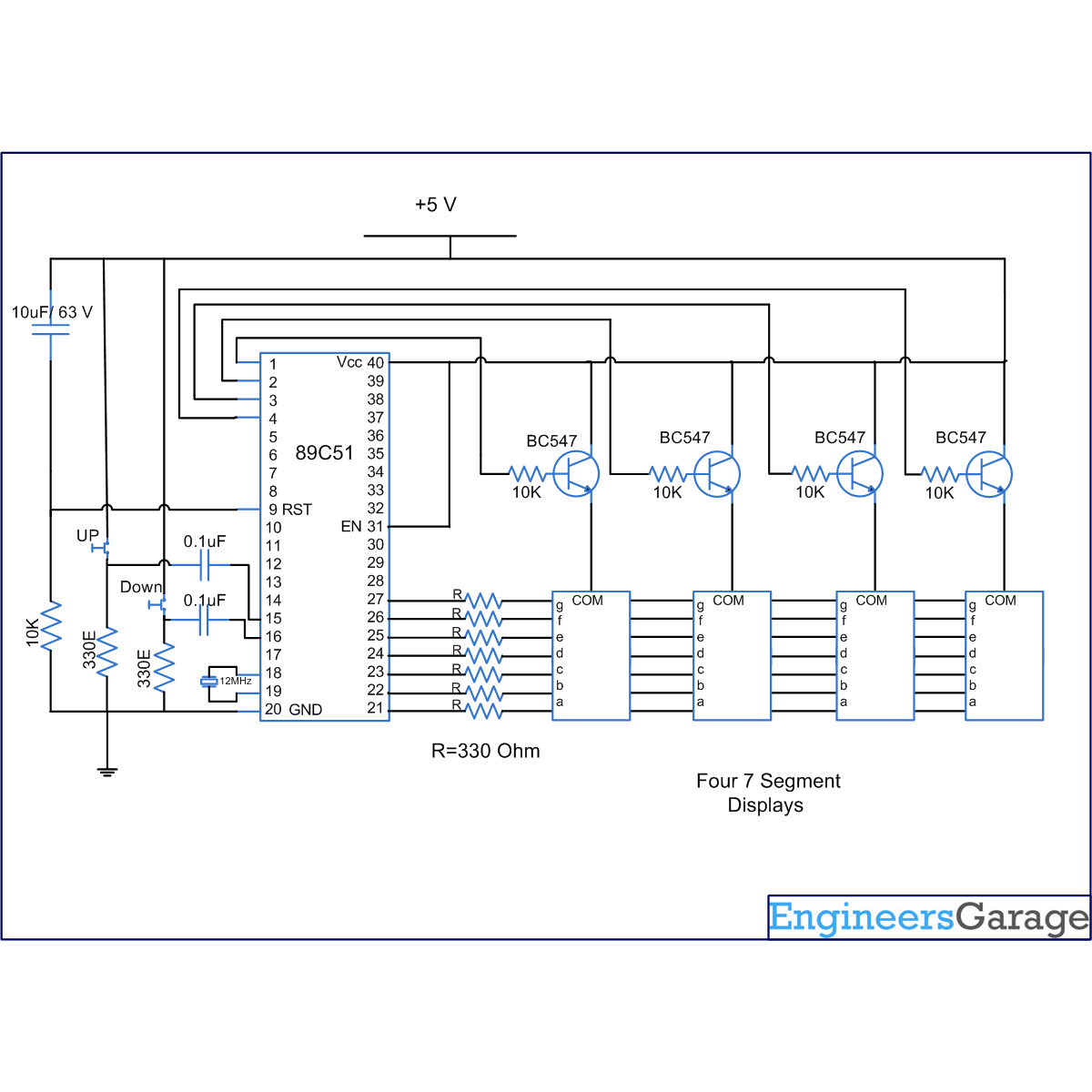
This article shows an easy to build up down counter. The counter is based around the 8051 microcontroller (AT89C51). Two switches are provided, one for increment and second for decrement. The switches can also be replaced by sensors to increment or decrement.
In this circuit, four seven segment display are used to show the value of count. The maximum value of count is 9999. The circuit uses the concept of multiplexing of seven segment to display the value of count. For more details on seven segment multiplexing, refer article titled “Seven segment multiplexing”.
In this circuit data output for the seven segment is given on the port P2 of the microcontroller AT89C51. The control signals for enabling the seven segment displays are given on pin no. 1,2,3,4 of microcontroller. The input of switches is taken on pin number P3.5 and P3.6. Switch connected on pin P3.5 is the increment switch and that at pin P3.6 is the decrement switch. The seven segment used here are common anode.
Whenever the increment switch is pressed the counter increments by one and when the decrement switch is pressed it gets reduced by one. The inputs of the microcontroller are made positive edge triggered by using a capacitor and resistor as shown in the circuit diagram. This helps in removing the problem of counting more than one on a single press of a switch. The value of the counter is displayed using the concept of seven segment multiplexing.
Project Source Code
###
//Program ro make a up down counter #include <reg51.h> #define msec 1 unsigned int num=0; sbit dig_ctrl_4=P1^3; //Declare the control or enable pins of seven segments sbit dig_ctrl_3=P1^2; sbit dig_ctrl_2=P1^1; sbit dig_ctrl_1=P1^0; unsigned int digi_val[10]={0x40,0xF9,0x24,0x30,0x19,0x12,0x02,0xF8,0x00,0x10}; unsigned int dig_1,dig_2,dig_3,dig_4,test=0; unsigned char dig_disp=0; sbit up=P3^5; //up pin to make counter count up sbit down=P3^6; //down pin to make counter count down void init() // to initialize the output pins and Timer0 { up=down=1; dig_ctrl_4 = 0; dig_ctrl_3 = 0; dig_ctrl_2 = 0; dig_ctrl_1 = 0; TMOD=0x01; TL0=0xf6; TH0=0xFf; IE=0x82; TR0=1; } void delay() //To provide delay a small time delay { TMOD=0x01; TL0=0x36; TH0=0xF6; TR0=1; while(TF0==0); TR0=0; TF0=0; } void display() interrupt 1 // Function to display the digits on seven segmnet. For more details refer seven segment multiplexing. { TL0=0x36; TH0=0xf6; P2=0xFF; dig_ctrl_1 = dig_ctrl_3 = dig_ctrl_2 = dig_ctrl_4 = 0; dig_disp++; dig_disp=dig_disp%4; switch(dig_disp) { case 0: P2= digi_val[dig_1]; dig_ctrl_1 = 1; break; case 1: P2= digi_val[dig_2]; dig_ctrl_2 = 1; break; case 2: P2= digi_val[dig_3]; dig_ctrl_3 = 1; break; case 3: P2= digi_val[dig_4]; dig_ctrl_4 = 1; break; } } void main() { init(); while(1) { if(up==0&&down==1) //check if up pin is pressed { test++; num=test; dig_4=num%10; num=num/10; dig_3=num%10; num=num/10; dig_2=num%10; dig_1=num/10; if(test==9999) test=0; } if(up==1&&down==0) //check if down pin is pressed { test--; num=test; dig_4=num%10; num=num/10; dig_3=num%10; num=num/10; dig_2=num%10; dig_1=num/10; if(test==0) test=9999; } } }###
Circuit Diagrams
Project Components
Project Video
Filed Under: 8051 Microcontroller.
Filed Under: 8051 Microcontroller.


Questions related to this article?
👉Ask and discuss on Electro-Tech-Online.com and EDAboard.com forums.
Tell Us What You Think!!
You must be logged in to post a comment.