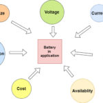
Nearly every electronic device today relies on a battery as a power source. The dc-dc converter plays a significant role in maintaining the working time of the battery. A buck-boost dc-dc converter is an ideal choice for the most efficient and reliable battery range.
The buck-boost converter provides the regulated voltage in the Lithium (Li-ion) battery range (a common battery choice for everyday devices, such as smartphones). These converters are suitable when the output voltage is higher or lower than the input voltage.
For this project, we’ll use a 595-TPS63051RMWR buck-boost integrated circuit (IC). This IC offers 3.3V/1A at the output for a full Li-ion battery range.
Basic design
Principle of operation
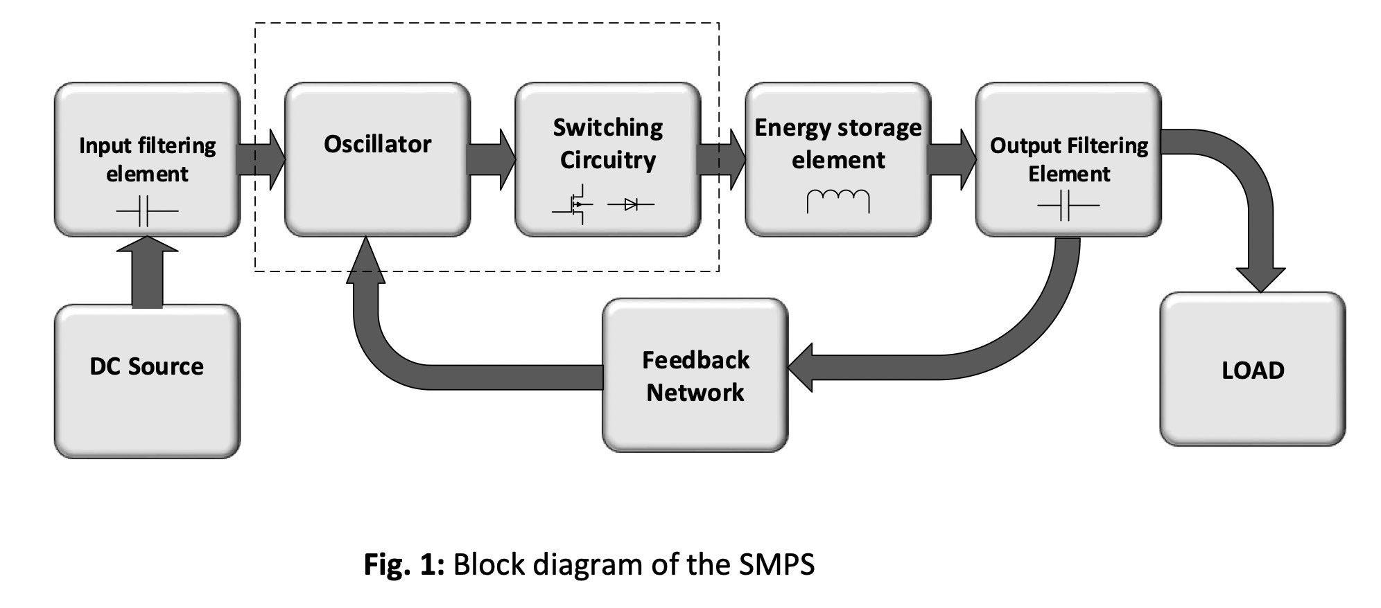
The switch mode IC works on the principle of a switching mechanism or the switched mode power supply (SMPS). The switch mode IC consists of an oscillator and switching circuitry. The oscillator works to generate the desired frequency, and the switching circuitry includes a transistor or diode as the switching element.
When the circuit is powered ON, the IC switches ON and OFF.
- During the ON period, the energy storage element charges, providing regulated voltage at the output.
- During the OFF period, the energy storage and output filtering element maintain the output voltage.
Parts needed

Circuit design
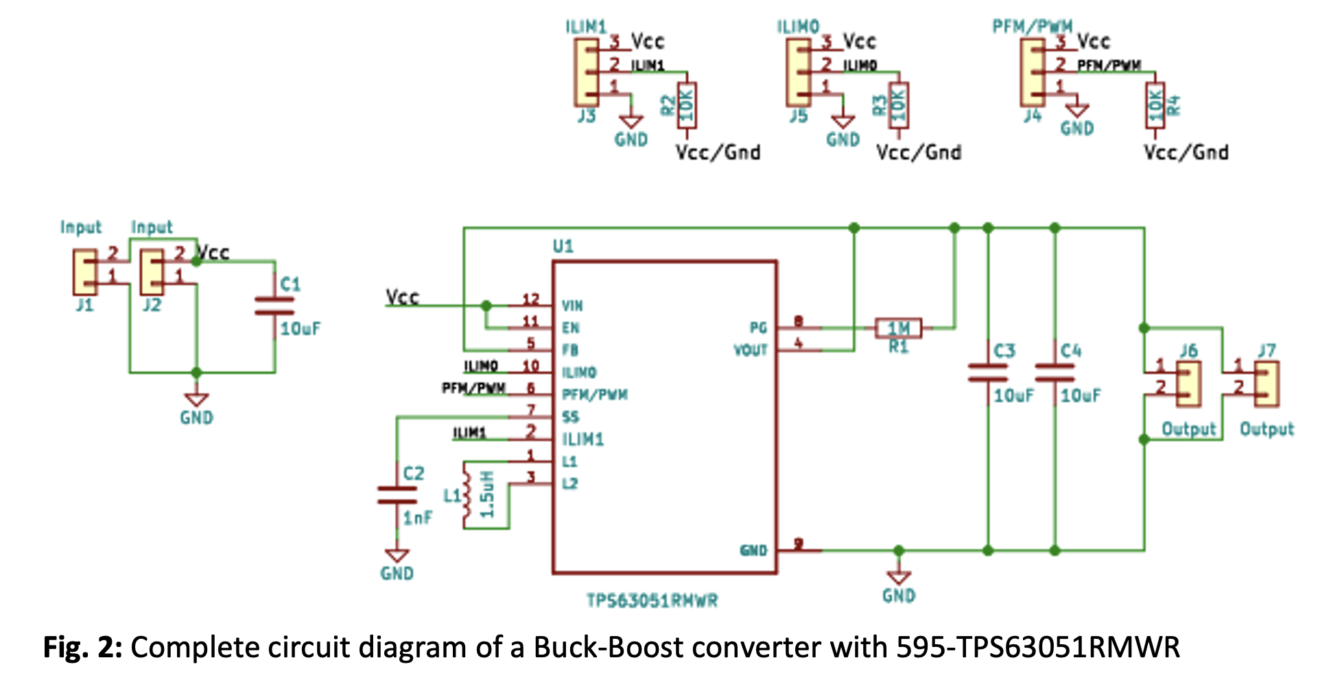
The following components are required to design the Buck-Boost converter circuit, along with a Buck-Boost IC.
1. Energy storing element – the inductor
Every switching regulator needs an energy-storing element to operate, and an inductor is a good choice. An inductor stores energy in the form of a magnetic field. However, before choosing the inductor, it’s important to calculate the current rating to avoid unregulated output or circuit saturation.
It’s necessary to calculate the peak current for the inductor during circuit operation using the below equation (Eq. 1).
Ipeak = (Iout / η(1-D)) + (Vin D/2fL)……Eq. 1
As we’re using a fixed 3.3V IC, it’s unnecessary to worry about the value of the inductor. Typically, for fixed switch mode ICs, the required value of the inductor is already in its datasheet. But it’s worth noting that we can change the value of the inductor and calculate its current rating using the above equation.
2. Filtering element capacitor
Capacitors filter and eliminate voltage spikes in the power supply. In a switching converter, the capacitor plays two roles:
- Provides filtering
- Serves as an energy source to manage the output transient response
Since the datasheet of this switch mode IC has a predefined value for the IN and OUT capacitors, we can use them directly in our circuit.
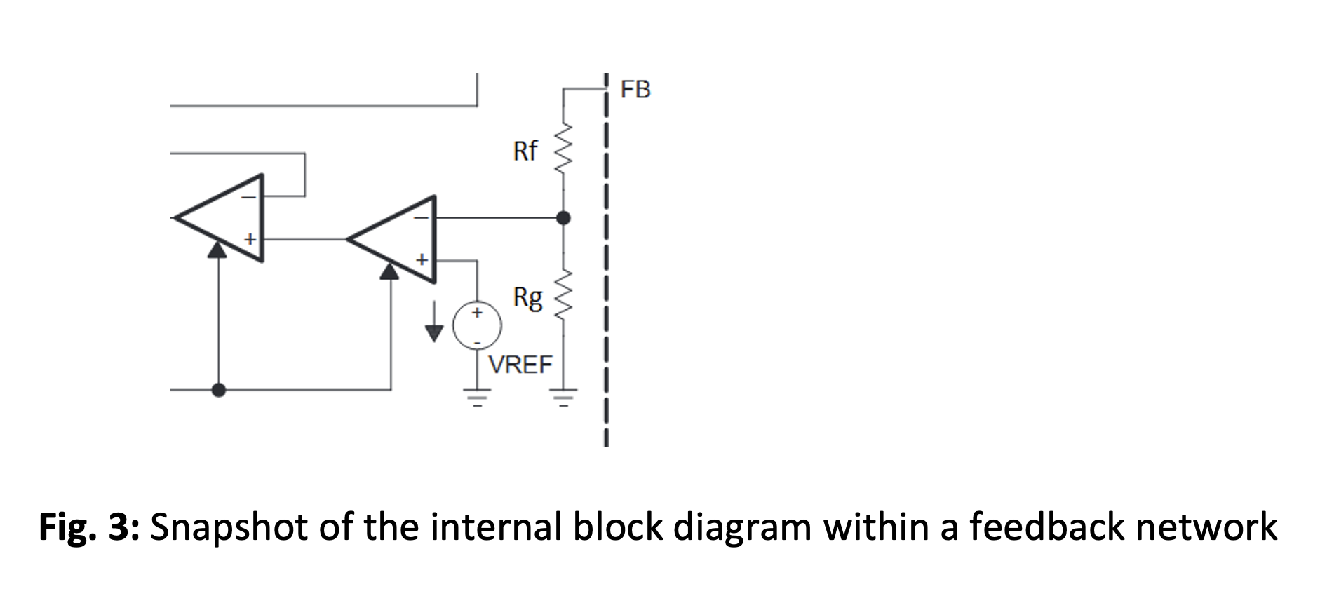
3. Feedback network-resistor divider
The feedback network helps regulate the output voltage. This network is a resistor divider. Some fixed switch mode IC incorporates this feedback network internally.
This completes the basic circuit requirement of the switch mode IC. Now, let’s discuss the extra features of the TPS63051RMWR IC.
IC features:
- Adjustable input current limit
- PFM/PWM mode
- Soft start
- Power good
- Overvoltage protection
- Thermal shutdown
- Output short-circuit protection
- Undervoltage lockout
Pin description:
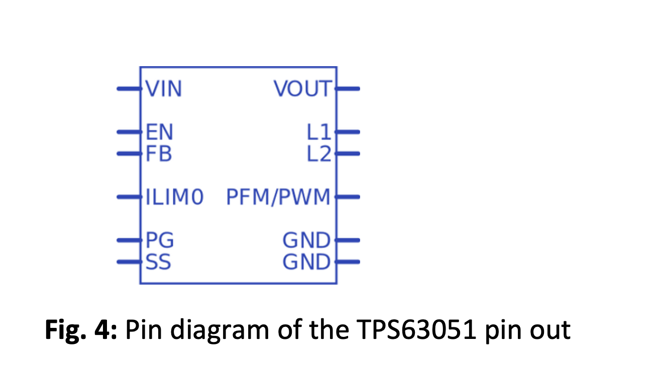
1. EN (Enable) – HIGH (voltage level to set high 1.2V-5.5) IC enable, LOW (maximum voltage to set LOW 0.3V) IC disable
ILIM1 and ILM0 – Sets the input current limit
 2. PFM/PWM and Efficiency
- PFM mode select – Low/0
- PWM mode select – High/1
Efficiency in both modes:
- PWM mode – Good efficiency for 350mA and above
- PFM mode – Good efficiency for lighter loads
To switch between these two modes, simply select the PFM/PWM mode.
3. SS (Soft Start) – Adjustable soft start. The circuit sets the default soft start time when this pin is left floating. The default period in Buck Mode – 280us and Boost Mode – 600us.
4. PG (Power Good) – This is an output pin that’s used to detect the power regulation of the system. The PG pin is only set to HIGH when the output is present, and it requires a pull-up resistor that connects to a voltage of less than 5.5V.
Converter output current limit
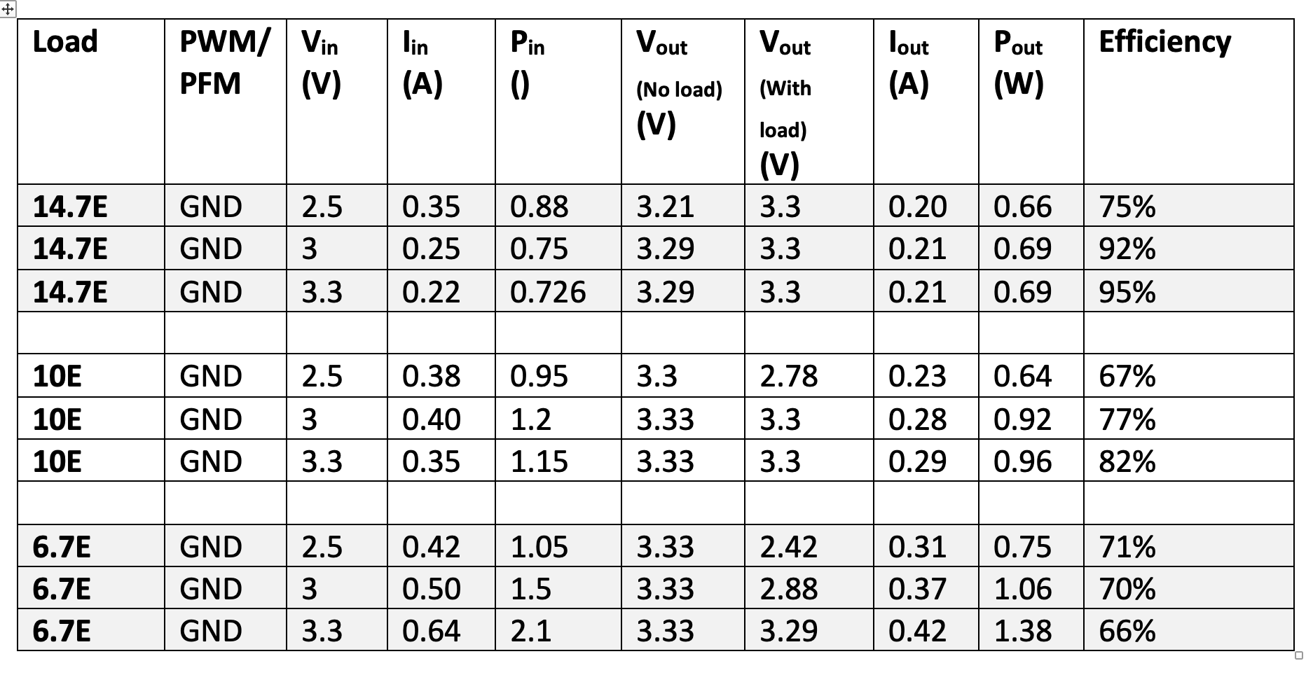
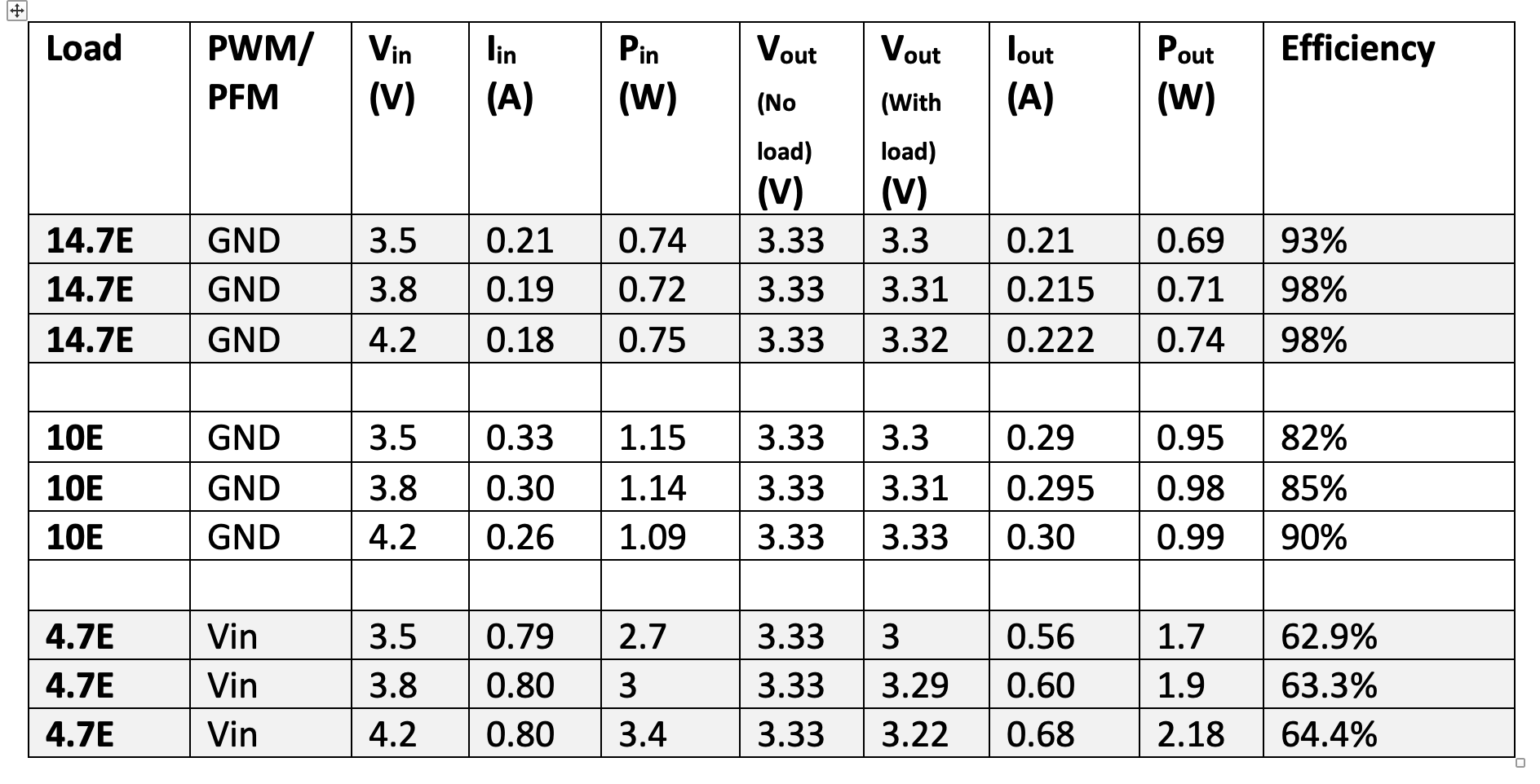
- For an input voltage, Vin = 2.5-3.3V Buck mode
- For an input voltage, Vin = 3.3-5.5V Boost mode
NOTE: In “Boost mode,” the maximum output current is 500mA and in “Buck mode,” it’s 1A.
The value of the output current is dependent on the input current. If we limit the input current (see above table), then the output will also be limited.
The equation for the Buck and Boost mode output current is:
- Boost output current, Iout = η.IIN(1-D)
- Buck output current, Iout = η.IIN/D
Key points
We have designed the circuit as per the application. However, initially, our circuit failed to work as expected. It provided zero voltage at the output terminals.
The potential causes:
- A soldering issue
- Faulty component(s)
- A faulty circuit design
- A PCB issue, so as shorting or continuity
After assessing these potential causes, we discovered a problem in the circuit design.
Review and rectification
The circuit design has three signal lines: PFM/PWM, ILIM1, and ILIM0. The signal lines provide a certain voltage to the device to enable or disable it, or to select a set mode on the device. These lines carry a low current (uA), which is generally known as the basing or quiescent current.
In our initial design, we connected the signal pins directly to the VCC, which allows for a high current across these pins. For ideal operation, we must add a pull-up resistor to limit the current, which resolves the problem.
Practical observation
- Current limit- IIN_max. VILM1 and VILM0 pins HIGH (at Vin)
- Boost mode, Iout(max) – 500mA
- Current limit- IIN_max. VILM1 and VILM0 pins HIGH (at Vin)
- Buck mode, Iout(max) – 1A
IC performance
Efficiency in Boost mode – 85% for load <200mA
– 70% for load >200mA
Efficiency in Buck mode – 96% for load <200mA
– 75% for load >200mA
Boost mode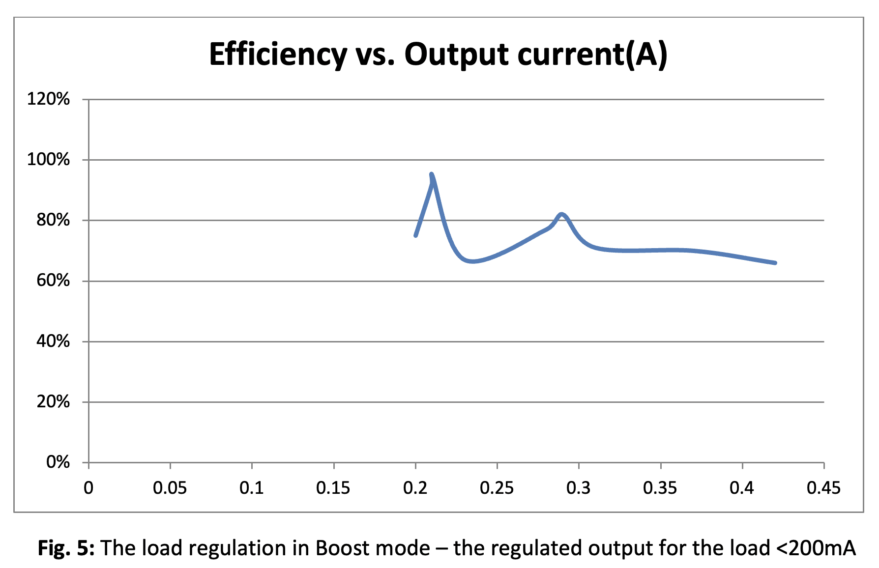
Buck mode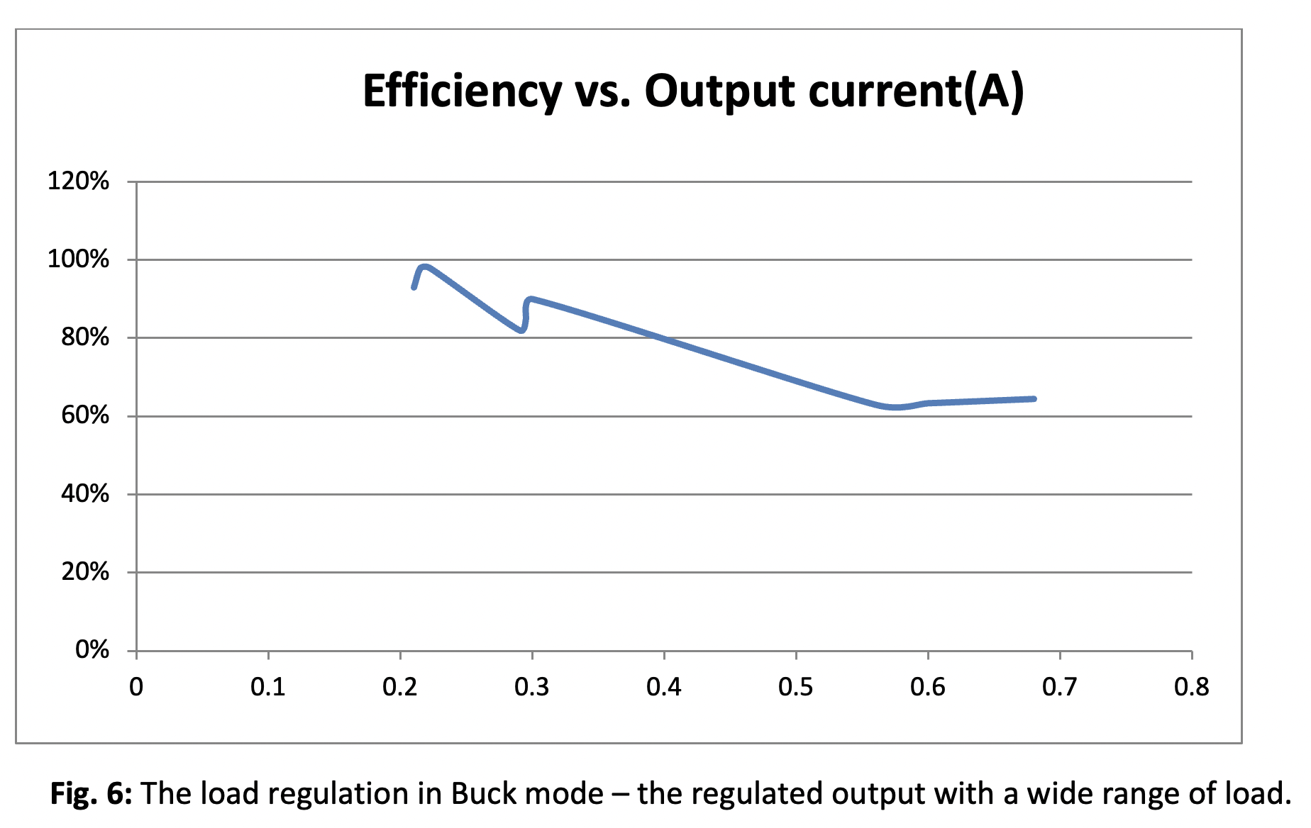
Thermal management
Every component dissipates heat when the current drawn from it increases. Sometimes the heat generated is so high that the component fails, so we need the heatsink to dissipate the extra heat.
Application
- Portable devices
- Regulated DC supply
- For use with a single Li-ion battery or two 1.5V coil cells
Precautions
A capacitor should be connected between the IN pin and the ground to regulate the DC input voltage. The circuit’s capacitor must have a higher voltage rating than the input supply voltage. Otherwise, the capacitor will leak current from its plates (and potentially burst) because of the excess voltage.
A few other important points:
- It’s critical to ensure the entire capacitor is discharged before working on a DC power supply.
- The current rating of the inductor must be 1.15 times greater than the output current. Do NOT use a higher voltage at the input than its operating input voltage range.
- Avoid shorting the output terminals — this will reverse the current flow in the IC, leading to fault or failure.
- Avoid shorting the input terminals — this will generate a large circuit current, and the circuit components will fail.
- Do not directly pull down or up the signal pins (PWM/PFM and ILIM1/ILM0 pin), as this will allow a high current to flow through the signal pin. Always connect a 10k resistance at signal pins to limit the quiescent current.
PCB design guidelines
- Keep the power traces thick and short
- Place the input and output capacitor as close as possible to the IC’s input and output pins
- Minimize the path length of the inductor
- Keep the voltage and switching nodes away from one another
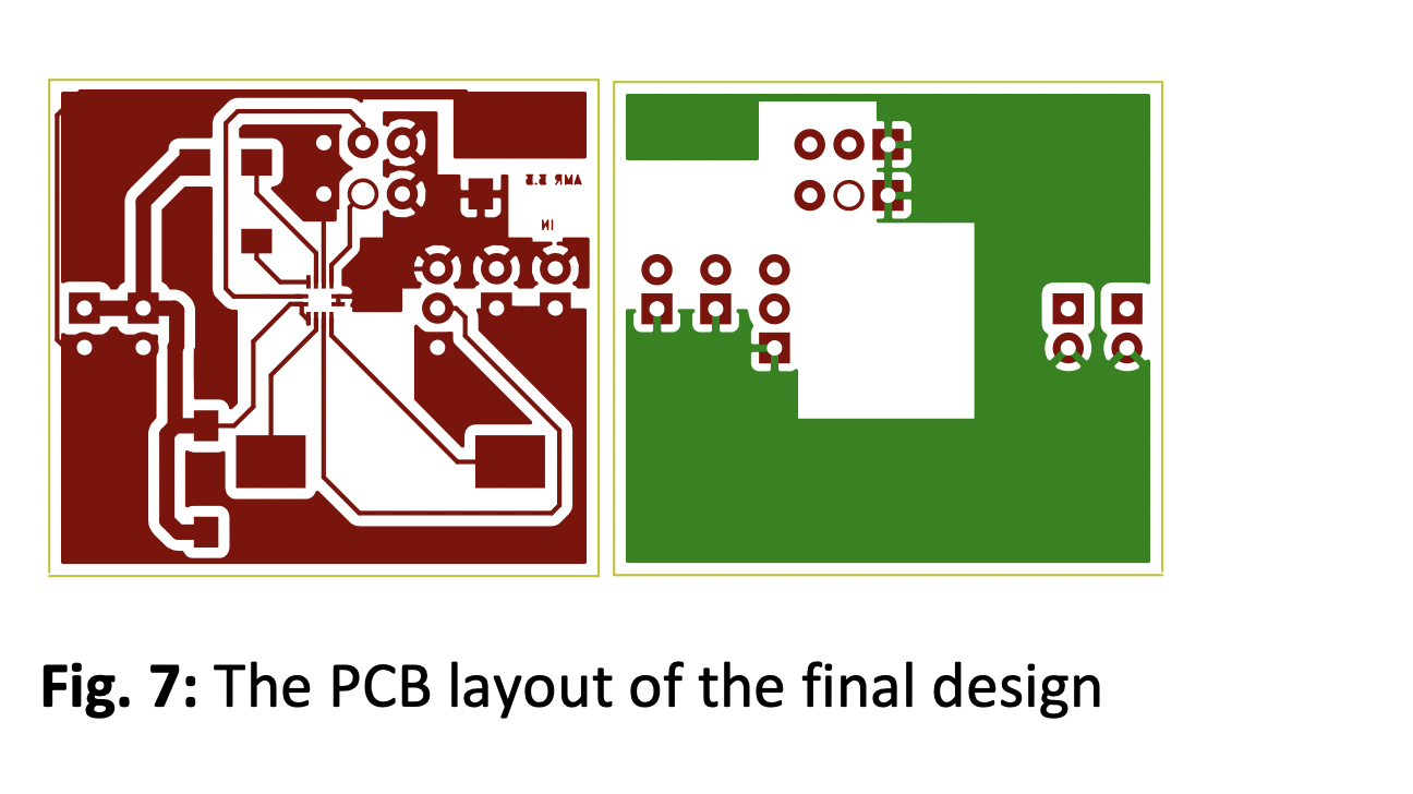
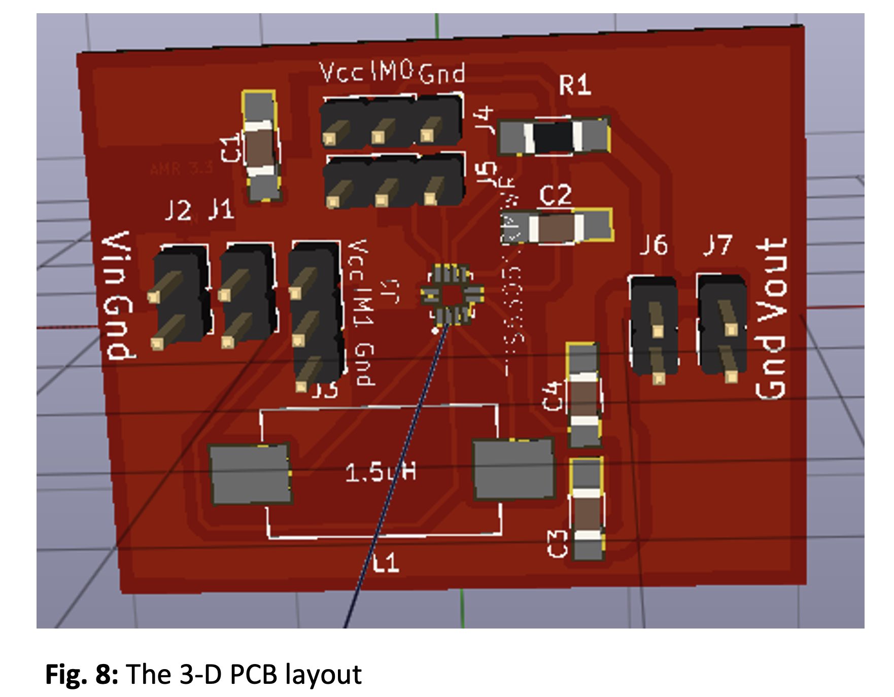
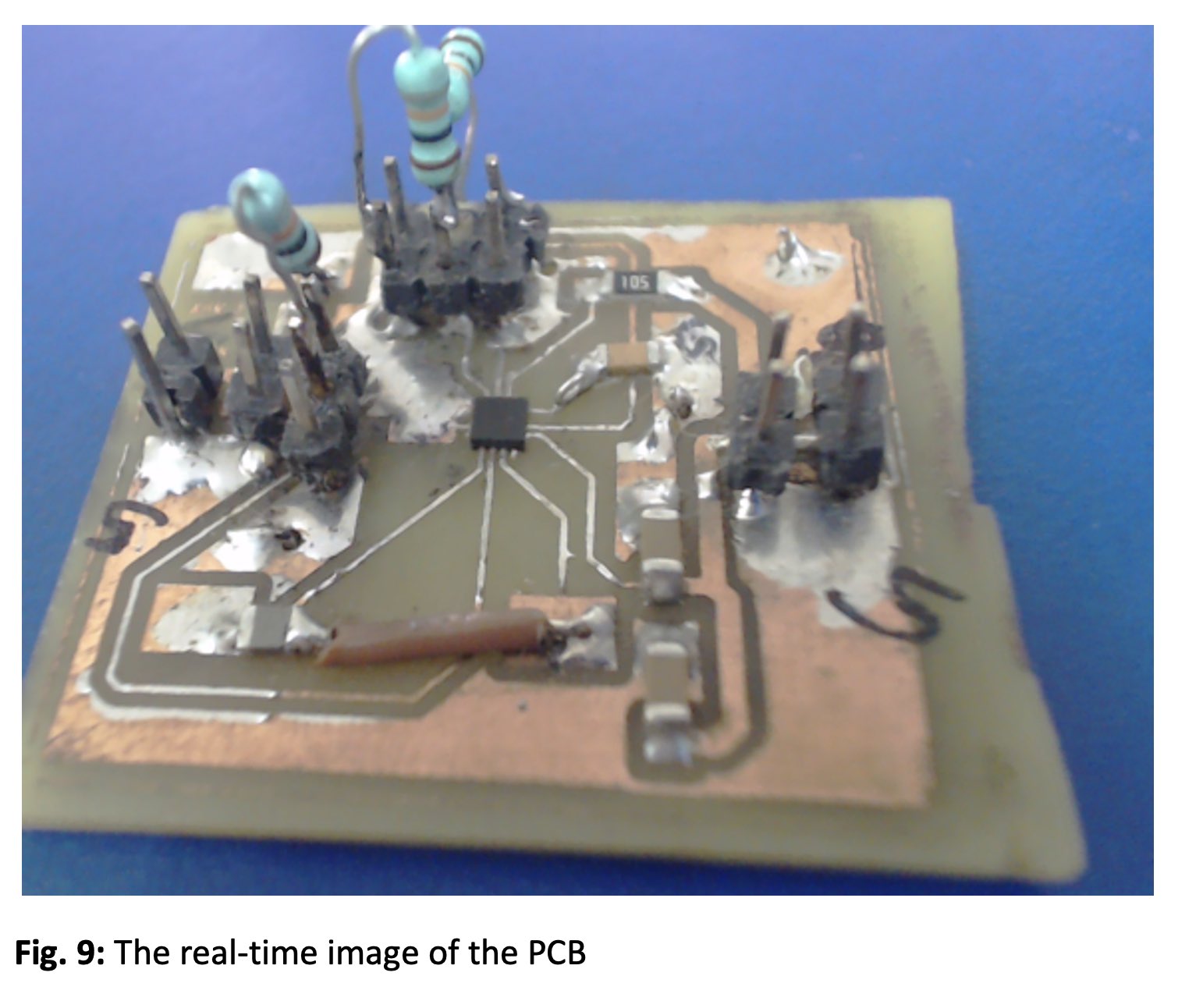
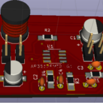
PCB layout
You may also like:


Filed Under: Batteries, Battery Management, Circuit Protection, Electronic Projects, Tutorials

Questions related to this article?
👉Ask and discuss on EDAboard.com and Electro-Tech-Online.com forums.
Tell Us What You Think!!
You must be logged in to post a comment.