The Arduino board also includes pins which can be used as external interrupt pins. The interrupt is a method to divert the Arduino from current block code execution to do another block of codes that needs immediate processing. The block of code which is written to process by an interrupt occurrence is called an Interrupt Service Routine (ISR). The Arduino will stop its current processing and start executing the ISR once an interrupt occurs. This article will give information about how Arduino external interrupt can be used to get the data from MCP2515 CAN controllers to save the time wastage in polling method for the data availability from CAN controller.
Prerequisites & Equipment:
You are going to need the following:
1. Two Arduino Board or Arduino clone(Here is a guide if you need)
2. A 5v TTL -UART Bluetooth module.
3. DHT11 Sensor.
4. Arduino IDE for the programming.
5. Two CAN Tranciever.
This article discusses the external interrupt based on the Arduino pro-mini board or Arduino clone which is programmed using the Arduino IDE version 1.0.1 downloaded for windows. The advantage of using this board is because it is very breadboard friendly and occupies very less space of a typical breadboard. The board also provides two external interrupt pins.
It is assumed that the reader has gone through the project how to get started with the Arduino and Cloning of Arduino and done all the things discussed in it.
The advantage of hardware interrupts is the Arduino will not waste most of its time “polling” or constantly checking the status of an IO pin.
Arduino has a number of interrupt sources, most of them tied into internal hardware modules such as timers and comparators, while some are tied into external hardware pins. Interrupts cvan be enabled by setting or clearing bits in internal registers.
There are four available functions for controlling interrupts with Arduino: attachInterrupt (), detachInterrupt (), interrupts (), and noInterrupts ().Most Arduino boards have two external interrupts: INTR0 and INTR1. The Arduino Mega has an additional four INTR2-INTR5.
ARDUINO EXTERNAL INTERRUPTS:
Atmega8,Atmega168 and Atmega328 micro-controller on the Arduino boards have two external interrupts available: INT0 and INT1, located on digital pins 2 and 3 respectively.
The Atmega8 supports four trigger modes for external interrupts:
-
L OW – a low level trigger
-
CHANGE – a change in level trigger
-
RISING – a rising edge of a level trigger
-
FALLING – a falling edge of a level trigger
For this tutorial we will be using a FALLING trigger mode. So, digital pin 2 will be connected to MCP2515 INT pin. Active High is maintained in the INT pin of MCP2515 and when new data is available it changes to low for a moment this can be captured by the Arduino external interrupt.
When configuring our external interrupt we will use the Arduino library function attachInterrupt(interrupt, function, mode). Here we are using this function with following three parameteres:
-
interrupt – This is the interrupt source, either 0 for INT0;
-
function – The function to call when the interrupt occurs(MCP2515_ISR);
-
mode – The trigger mode as specified above (FALLING);
Here we are using Humidity sensor in the transmitter side and receiver side LCD to display the Humidity and temperature using interrupts.
The block diagram of the project is shown in Figure. The system is made up of two CAN nodes. DISPLAY node that reads the temperature from the CAN Bus and displays it on an LCD. This process is repeated continuously. The other node called COLLECTOR node reads the temperature an humidity from the DHT11 temperature sensor.

Fig. 1: Block Representation of CAN Bus Interfacing two Arduino Uno Boards
The DISPLAY Processor:
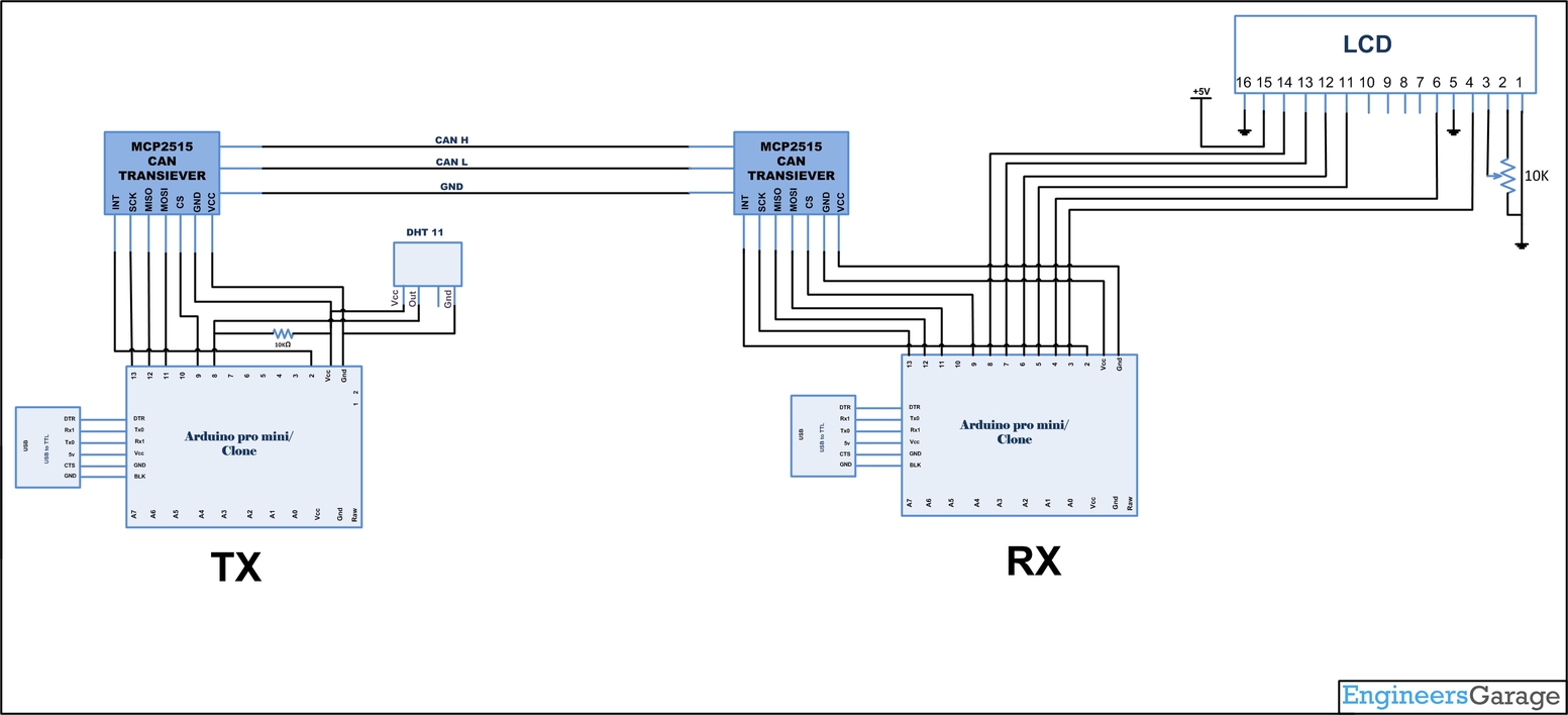
DISPLAY processor consists of an Arduino with a MCP2515 CAN module and an TJA1040 transceiver chip. The Microcontroller is operated from a 16MHz crystal. And MCP2515 has an SPI interface which is used to connect using SPI pins in Arduino. The MCP2515 INT pin is connected to the Arduino Interrupt pin, Every time when there is a new frame MCP2515 INT pin create a LOW pulse which is captured by the Arduino INT pin and the data is received, processed and displayed in the LCD. The Pins CANH and CANL of the transceiver chip are connected to the CAN bus.
The COLLECTOR Processor:
The COLLECTOR processor consists of an Arduino with a MCP2515 CAN module and an TJA1040 transceiver chip.The DHT11 is chosen because it is lab calibrated, accurate and stable and its signal output is digital. The DHT11 is a basic, ultra low-cost digital temperature and humidity sensor. It uses a capacitive humidity sensor and a thermistor to measure the surrounding air, and spits out a digital signal on the data pin (no analog input pins needed). It’s fairly simple to use, but requires careful timing to grab data. The only real downside of this sensor is you can only get new data from it once every 2 seconds, so when using our library, sensor readings can be up to 2 seconds old.
Pin Name Description
1 VDD Power supply 3 – 5.5 V DC
2 DATA Serial data output
3 NC Not connected
4 GND Ground
Wiring:
Connect the sensor to the Arduino as shown below
DHT11 Arduino
Pin 1 Vcc
Pin 2 Analog0( And a 10K pull up resistance)
Pin 4 Gnd
Install the DHT11 library and Modify:
Download this zipped file and unzip it under the libraries directory of the Arduino IDE folder. For example, for my computer’s setup, the directory is
XXXarduino-1.0.1libraries
After copying files across, the directory
XXXarduino-1.0.1librariesDHT
should have the following two files: dht.h and dht.cpp
Reading Temperature and Humidity data and transmitting it in the CAN Bus:
Load the program TX.ino after you save it onto your computer and open it in Arduino IDE .
-
Compile the program in the Arduino IDE
Temperature and Humidity values can be get by the following commands using the DHT library.
float h = dht.readHumidity();
float t = dht.readTemperature();
The following function is used to send the values to the can bus. Detailed instruction can be found here.
CAN.sendMsgBuf(0x70,0, 2, stmp);
Receiving CAN data and displaying in an LCD:
Load the program RX.ino after you save it onto your computer and open it in Arduino IDE .
-
Compile the program in the Arduino IDE
The following function is used to receive the values from the CAN bus and to display on an LCD. Detailed instruction can be found here.
CAN.readMsgBuf(&len, buf);
Loading software for Arduino:
If you are new to Arduino you can start with here. You have to start with the Arduino IDE (Integrated Development Environment) from Arduino . Download the code from below link and upload it to the Arduino board.
Hardware assembly:

Fig. 2: Image showing DHT-11 sensor interfaced with Arduino Transmitter Circuit on one side of CAN Bus

Fig. 3: Image showing LCD Module Interfaced with Arduino Receiver Circuit on Other side of CAN Bus

Fig. 4: Prototype of Arduino to Arduino Communication on CAN Bus
Make the circuit as is given by the circuit diagram. Make the circuit with your selected parts and connect the motors to the circuit.
Circuit Diagrams
Project Video
Filed Under: Electronic Projects
Filed Under: Electronic Projects

Questions related to this article?
👉Ask and discuss on Electro-Tech-Online.com and EDAboard.com forums.
Tell Us What You Think!!
You must be logged in to post a comment.