This Timer can give a time delay from 10 minutes to 12 hours. The time delay can be selected using a Rotary switch and when the timing cycle completes, relay energizes and remains latched till the circuit resets. This circuit finds various applications like battery charging or to control lab equipments. Timing cycle is not so precise and a variation of one to 3 minutes can be expected.
Working of the Circuit
Main element of the circuit is the popular Binary counter IC CD4060. It is the 14 stage Oscillator cum binary counter cum frequency divider with an inbuilt oscillator which oscillate depending on the values of the resistor connected to its pin 10 and capacitor at pin 9.

Fig. 1: Image of Binary counter IC CD4060
When the timing cycles completes, output of the IC goes high. This output can be used to drive loads such as relay through a driver transistor. Since IC 4060 is a binary counter, each output turns high with a time delay double that of the previous one and remains high for the same duration. So any of the 10 outputs can be used to get the required time delay. Output Q 10 is omitted in the IC itself so that the time delay of Q11 (Pin 1) output is 4 times higher than that of Q9 (Pin 15).
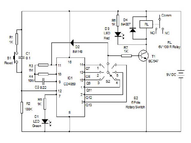
At power on IC1 resets through C1 and R2 and starts oscillations. Q3 output (Pin7) turns high first which is indicated by the blinking of Green LED. Each output then turns high as follows:
10 minutes Q7 (Pin 14)
20 minutes Q8 (Pin 13)
45 minutes Q9 (Pin15)
3 hours Q11 (Pin 1)
6 hours (Q12 (Pin2)
12 hours (Q13 (Pin3)
When the output turns high, transistor T1 conducts and activates the relay. Load can be connected through the Common and NC contacts of the relay so that when the relay turns on, load disconnects. Red LED indicates the activation of relay. When the output turns high, diode D2 conducts and inhibits the oscillator and IC1 latches with the high output and the relay remains energized till resetting. Push switch can be used to reset IC1 if required. Circuit can be powered using 9 volt DC.
Components
Resistors
R1, R5, R6, R7 1K, R2 100K, R3 1M, R4 10M,
Capacitors
C1 0.1, C2 0.22
Diodes
D1Green LED, D2 IN4148, D3 Red LED, D4 IN4007
Transistor
T1 BC 547
Integrated Circuit
IC1 CD 4060
Relay
RL 6 Volt 100 Ohms
Switch
S1 Push to On, S2 6 Pole Rotary Switch
Circuit Diagrams
Filed Under: Electronic Projects

Questions related to this article?
👉Ask and discuss on EDAboard.com and Electro-Tech-Online.com forums.
Tell Us What You Think!!
You must be logged in to post a comment.