Voltage regulator is a device which provides fix output voltage in spite of the variable input voltage supplied. It is a three terminal device. Voltage regulator basically comes in two different series: 78XX and 79XX. Voltage regulator under 78XX series are designed for positive inputs i.e. if while 79XX series are designed for negative inputs. In market variety of voltage regulators are available with output as 6V, 9V, 12V, 15V etc. Voltage regulator can also withstand over current drawn due to short circuit or overheating. It will cut off the circuit before damage occurs. One must take care while mounting the regulator because reverse polarity may destroy the regulator.
Pin configuration of negative and positive voltage regulator are shown in fig.
[[wysiwyg_imageupload:8289:]]
Fig. 1: Image Of 78XX and 79XX Voltage Regulator
Voltage regulator is a device which provides fix output voltage in spite of the variable input voltage supplied. It is a three terminal device. Voltage regulator basically comes in two different series: 78XX and 79XX. Voltage regulator under 78XX series are designed for positive inputs i.e. if while 79XX series are designed for negative inputs. In market variety of voltage regulators are available with output as 6V, 9V, 12V, 15V etc. Voltage regulator can also withstand over current drawn due to short circuit or overheating. It will cut off the circuit before damage occurs. One must take care while mounting the regulator because reverse polarity may destroy the regulator.
Pin configuration of negative and positive voltage regulator are shown in Fig 1.
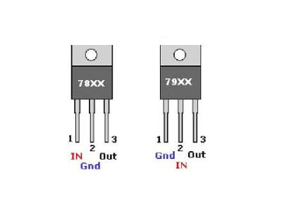
Fig. 1: Image Of 78XX and 79XX Voltage Regulator
As we know that output of regulator is fixed but with the help of voltage divider rule we can use 5V regulator to deliver 12V. But reverse is not possible that is we cannot obtain 5V from 12V regulator.
How we have calculated the value of resistor for different voltages-
Suppose value of resistor connected between com and output pin of regulator be 470ohm(R1).This means we have 10.6mA current (because V =5V and V = IR) available between pin, com and output. There would be some stand-by current of about 2.5mA which will be available between rotary switch and ground. Therefore total current available will be approx. 13.1mA. Now, let’s say we want 5V to 12V from this circuit. For minimum 5V, we will directly get this from regulator output. But if you want maximum 12V, then apart from 5V,additional 7V would require selection of appropriate resistor.
Here R =?
V = 7V
I =13.1mA
Therefore V =I*R
R = 543ohm
Therefore, we have to connect resistor of 543ohm with 470ohm to get the desire output of 12V. But resistor of this value might not be easily available, so we can use resistor that has values near to it viz. 560ohm.
Now if you want to obtain different voltage between 5V and 12V use different values of resistor like if you want to obtain 6V then-
V =6V
I = 10.6mA
R = 6V/10.6mA
R = 566ohm
But we have already connected resistor R1 of 470ohm so, for 6V we have to use resistor value =100ohm( 566- 470ohm= 96 approx 100ohm). Similarly, you can calculate different values of resistor for obtaining different voltages.
In this circuit we have used different resistors to obtain different values of voltage. You can also use a variable resistor to obtain the different values of voltage with a single resistor.
You may also like:
Designing a Switched Mode Power Supply (SMPS)
+/- 1.25V to +/-22V 1A adjustable power supply
1.25V – 25V Variable power supply using bridge rectifier
Variable power supply and charger with emergency light
Un-interruptible Bench-top DC Power Supply With Display
Circuit Diagrams
| Circuit-Diagram-Variable-Power-Supply-From-Fixed-Voltage-Regulator |
Project Components
You may also like:

Circuit Diagrams
Project Components
Filed Under: Circuit Design

Questions related to this article?
👉Ask and discuss on EDAboard.com and Electro-Tech-Online.com forums.
Tell Us What You Think!!
You must be logged in to post a comment.