While measuring voltage and current with multi-meter, the probes have to be changed its position carefully. There is a probability of damaging the multi-meter, if voltage is measured in high current mode by mistake. In case, both voltage and current to be measured at a time, we have to use two multi-meters and care should be taken while wiring both the multi-meters. VAT meter is combination of Voltmeter, Ammeter and Thermometer. It can measure voltage and current simultaneously along with the temperature.
The project is built on ATMega8 So Reader should have knowledge of how to start with AVR and interface LCD with AVR. It used ACS-712 current sensor to measure the current and voltage is measured by ACD terminal. There is two temperature sensor is used in the circuit which can measure temperature of two different places like Transformer, Voltage regulator or any heating components. All data can observable on 16×2 LCD display.
This project can measure and display maximum voltage up to 50Volts DC and maximum current up to 20Amps DC. When Voltage is exceeds 45VDC or current exceed 15A or temperature exceed 70 degree then the display blinks parameter near particular value and beep sound is generated.
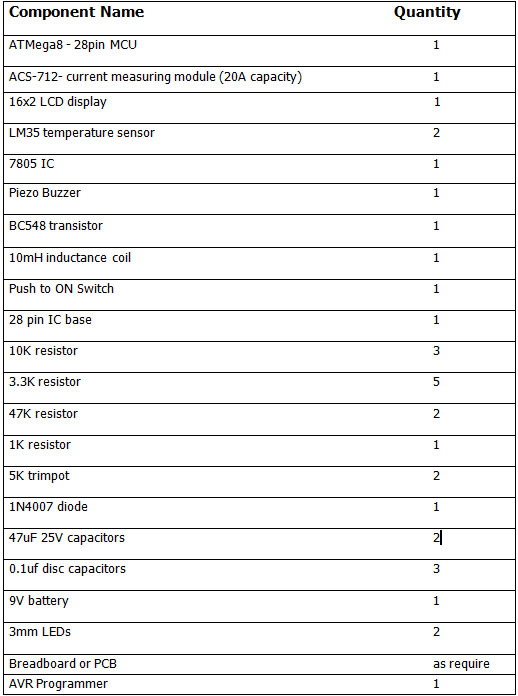
Components Required –
Block diagram –
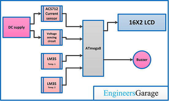
Fig. 1: Block Diagram Of VAT METER using ATMega8
Circuit Connections –
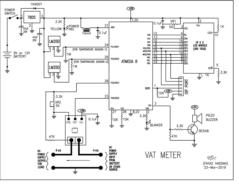
This device is based on AVR ATMega8. ATMega8 is an 8 bit microcontroller that can operate up to 16 MIPS Throughput at 16 MHz clock. Here we are using internal RC oscillator of ATMega8 which provides fixed 1.0 2.0 4.0 or 8.0 MHz clock so set your ATMega8 to 1MHz internal RC oscillator.
ATMega8 is interfaced with 16×2 LCD, L M35 and ACS712 to make the device. There is a Trimpot (Shown as VR1 in the circuit diagram) which is used to adjust the contrast of LCD. There is a Yellow LED that is interfaced parallel to the whole circuit which is used to indicate that the power supply for circuit is working properly. There is a blinker connected at bit 0 of port D of ATMega8 which indicates, the MCU is working.
Two LM35 temperature sensors are used to get state of temperature at two different places. Both LM35 is connected at the bit 1, 2 of port C of ATMega8 which is ADC pin 1 and 2. ACS712 Current sensor is used to measure the current via connected in series with DC power supply. The OUT pin of ACS712 is connected to bit 0 of port C of ATMega8 which is ADC pin 0. The voltage is measured by bit 3 of port C of ATMega8 which is ADC pin 3. There is a Trimpot (Shown as VR2 in the circuit diagram) which is used to calibrate the voltage.
BC548 transistor is used to drive buzzer. The base of transistor is connected with bit 1 of port D of ATMega8. Collector of transistor is connected with buzzer and emitter is connected to ground. AREF or 21th pin of ATMega8 is connected to the 5v via 10mH inductor and also there is 0.1uf capacitor connected in between ground and AREF. The entire circuit operates on 5V DC which may obtain from 5V power bank or 9V battery with 5V regulated power supply using 7805 IC. The internal RC oscillator (1 MHz) used with ATMega8 so no need to add external oscillator.
How circuit Works –
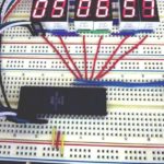
After assembling the circuit, the ISP port of ATmega8 must be connected to any AVR programmer and VATmeter.hex file should be flashed in the microcontroller. Then, disconnect the circuit from the AVR programmer. Now the device is ready for operation. When the Device is powered ON, the blinker LED start blinking and LED displays “Welcome to VAT METER”. After few second LCD comes in stable state that displays Voltage, ampere and temperature of both sensor and it update data as update in sensor input.
While we connect the DC power source in series with ACS712 current sensor as shown in circuit diagram. The LCD shows the voltage and current of battery. Make sure the Load is connected in series with battery and ACS712 current sensor so current can be measured across the Load. Temperature sensor can be placed near heating component so it will measure temperature.
If the temperature exceeds 70 degree Centigrade or Voltage exceeds 45VDC or Current exceeds 15ADC then, the display blinks the parameter near the particular value and a beep sound is generated via buzzer.
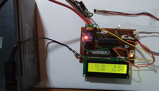
Fig.1: Image showing Working of VAT METER
Programming Guide –
This device is based on AVR ATMega8 and it is programmed with embedded C using AVR Studio 4. Other programming tools like Atmel Studio or Notepad++ can also be used to write and compile the code. The ATMega8 is programmed to measure Voltage, Current and temperature at same time in single display. This project can measure voltage up to 50Volts DC and maximum current up to 20Amps DC.
Constants used in the code –
#define F_CPU 1000000L :- Constant used to define clock frequency of the MCU
#define BLINKER 0b00000001 :- define blinker LED to bit 0 of port D
#define ALARM 0b00000010 :- define buzzer connected at bit 1 of port D
#define LCD_DP PORTB :- Port B defined as LCD data control port
#define LCD_CP PORTD :- Port D is defined as control port of LCD
#define LCD_EN 0b10000000 :- EN pin of LCD is connected at 7 bit of port D
#define LCD_RS 0b01000000 :- RS pin of LCD is connected at 6 bit of port D
Variable used in code –
long AMPFACTOR = 488; :- To calculate ampere value to ADC value
int VOLTS=0; :- To store voltage value
long AMPS=0L; :- To store current value
int TEMP1=0; :- To store temperature from first sensor
int TEMP2 = 0; :- To store temperature from second sensor
char DST[8]; :- To display value on LCD
long A=0; :- To initially store ADC vale
int loop = 0; :- To control the blink of parameter on LED
int alarm = 0; :- To control the buzzer
int temparray1[5]={25,25,25,25,25}; :- To Store 5 value of temperature for average temperature
int temparray1pos=0; :- To Select the temperature array value
int temparray2[5]={25,25,25,25,25}; :- To Store 5 value of temperature for average temperature
int temparray2pos=0; :- To Select the temperature array value
Header file and libraries used in the code –
#include <avr/io.h> :- Standard AVR header for input/output
#include <util/delay.h> :- Standard AVR header to provide time delays
Function used in the code –
initPorts :- To initialize port as input or putput
LCD_enable :- To control the EN pin of LCD
LCD_WriteCmd :- write command for LCD
LCD_init :- To initialize LCD at beginning
LCD_RowCol :- To Set the cursor position
LCD_ClrScr :- To clear the LCD display
LCD_writeCh :- Write character on LCD display
LCD_writeStr :- Write String on LCD display
ADC_init :- To initialize ADC
ADC_read :- Read ADC value
showValue :- Show value in specific format
_delay_ms :- For time Delay
Algorithm –
The code for this VAT METER using ATMega8 works as follow.
When the VAT Meter circuit is powered on, first of all , the port is initialized that set the port B and port D as output . the port C as set as input.
void initPorts ( )
{
DDRB = 0xFF;
DDRD = 0xFF;
DDRC = 0x00;
}
After initialization of port, the blinker LED set to High for some delay and then it inverted (set to LOW). Also LCD is initialized.
PORTD |= BLINKER;
_delay_ms ( 2000 );
LCD_init ( );
_delay_ms ( 100 );
PORTD &= (~BLINKER);
Firstly LCD is Cleared to remove any type of garbage value. Then set cursor to print massage “Welcome to” in first row and “VAT METER” in second row.
LCD_ClrScr();
LCD_RowCol ( 1, 1 );
LCD_writeStr ( “Welcome to” );
LCD_RowCol ( 2, 7 );
LCD_writeStr ( “VAT METER” );
Now ADC is initialized and reading all ADC channel values. Then LCD cleared that remove welcome massage.
ADC_init ( );
_delay_ms ( 2000 );
for ( int i=0; i<10; i++ )
{
ADC_read ( i/2 );
}
LCD_ClrScr();
We entered in while loop, here loop variable used that blink the parameter on LCD with every cycle while any value exceeded it’d defined value. alarm set to LOW. Blinker LED set to blink for every cycle which indicates MCU is working.
if (loop==0)
loop = 1;
else
loop = 0;
alarm = 0;
PORTD ^= BLINKER;
Read ACD value from channel 3 and store it in A variable. Divided ADC value by 2 in order to maintain max range approximate 50 volt. Cursor of LCD set to it’s position to print the value in specific format. If voltage vale is exceeded the 45 Volt range the “V” parameter on LCD will blink and buzzer makes beep sound.
A = ADC_read(3);
_delay_ms ( 5 );
LCD_RowCol ( 1, 1 );
VOLTS = A / 2;
showValue ( VOLTS );
if (VOLTS>450 && loop==0)
{
LCD_writeStr ( ” ” );
alarm = 1;
}
else
LCD_writeStr ( “V ” );
Now set A to zero for reading another ADC value from channel 0. Some calculation require to convert ADC value into Ampere value. once we got the ampere value just print on LCD . When Current exceed the defined range of 15 amp then it blink parameter on LCD and buzzer makes beep sound.
A = 0;
ADC_read ( 0 );
_delay_ms ( 5 );
for ( int i=0; i<10; i++ )
{
A = A + ADC_read ( 0 );
_delay_ms ( 5 );
}
A = 5110-A;
AMPS = (A * AMPFACTOR) /10000L;
LCD_RowCol ( 2, 1 );
showValue ( AMPS );
if ( (AMPS>150 || AMPS<-150) && loop==0)
{
LCD_writeStr ( ” ” );
alarm = 1;
}
else
LCD_writeStr ( “A ” );
Set A to zero and read value From ADC channel 1. Here 5 temperature values is taken for every cycle in order to take average temperature value. When temperature value exceeds 70 degree it blinks parameter on LCD and buzzer will makes beep sound.
A = 0;
ADC_read(1);
_delay_ms ( 5 );
for ( int i=0; i<10; i++ )
{
A = A + ADC_read ( 1 );
_delay_ms ( 5 );
}
TEMP1 = A/2;
temparray1[temparray1pos++] = TEMP1;
TEMP1 = (temparray1[0] + temparray1[1] + temparray1[2] + temparray1[3] + temparray1[4] )/5;
if (temparray1pos>4)
temparray1pos = 0;
LCD_RowCol ( 1, 9 );
showValue ( TEMP1 );
if (TEMP1>700 && loop==0)
{
LCD_writeStr ( ” ” );
alarm = 1;
}
else
{
LCD_writeCh ( 223 );
LCD_writeCh ( ‘C’ );
}
Set A to zero and read value From ADC channel 2. Here 5 temperature values is taken for every cycle in order to take average temperature value. When temperature value exceeds 70 degree it blinks parameter on LCD and buzzer will makes beep sound.
A = 0;
ADC_read(2);
_delay_ms ( 5 );
for ( int i=0; i<10; i++ )
{
A = A + ADC_read ( 2 );
_delay_ms ( 5 );
}
TEMP2 = A/2;
temparray2[temparray2pos++] = TEMP2;
TEMP2 = (temparray2[0] + temparray2[1] + temparray2[2] + temparray2[3] + temparray2[4] )/5;
if (temparray2pos>4)
temparray2pos = 0;
LCD_RowCol ( 2, 9 );
showValue ( TEMP2 );
if (TEMP2>700 && loop==0)
{
LCD_writeStr ( ” ” );
alarm = 1;
}
else
{
LCD_writeCh ( 223 );
LCD_writeCh ( ‘C’ );
}
If alarm variable IS high Then produce beep sound via port D’s pin 1.
if (alarm)
PORTD |= ALARM;
_delay_ms ( 150 );
PORTD &= (~ALARM);
_delay_ms ( 60 );
Check out the complete code and quickly start building this exciting project.
You may also like:
Project Source Code
###
//Program to /* filename : VATmeter.C author : f.hassan date : 10-03-2018 MCU : ATmeaga8 display : LCD 16x2 */ #define F_CPU 1000000L #define BLINKER 0b00000001 #define ALARM 0b00000010 //================================================================================= #include#include #define LCD_DP PORTB #define LCD_CP PORTD #define LCD_EN 0b10000000 #define LCD_RS 0b01000000 long AMPFACTOR = 488; // for 20A int VOLTS=0; long AMPS=0L; int TEMP1=0; int TEMP2 = 0; char DST[8]; //============================================================================= void initPorts ( ) { DDRB = 0xFF; DDRD = 0xFF; DDRC = 0x00; } //============================================================================= void LCD_enable ( ) { LCD_CP |= LCD_EN; _delay_us(50); LCD_CP &= (~LCD_EN ); _delay_us(30); } //=========================================================================== void LCD_WriteCmd ( unsigned char cmd ) { LCD_CP &= (~LCD_RS ); LCD_DP = cmd; LCD_enable ( ); } //============================================================================= void LCD_init( ) { unsigned char initval = 0x30; _delay_ms ( 50 ); LCD_WriteCmd ( 0x30 ); _delay_ms ( 20 ); LCD_WriteCmd ( 0x30 ); _delay_us ( 200 ); LCD_WriteCmd ( 0x30 ); _delay_ms ( 100 ); initval |= 0b00001000; initval |= 0b00000100; LCD_WriteCmd ( initval ); _delay_ms ( 25 ); LCD_WriteCmd ( 0x0C ); _delay_ms ( 25 ); LCD_WriteCmd ( 0x06 ); _delay_ms ( 50 ); } //============================================================================= void LCD_RowCol ( unsigned char R, unsigned char C ) { switch (R) { case 2: LCD_WriteCmd ( 0xC0 + C-1 ); break; case 1: default: LCD_WriteCmd ( 0x80 + C-1 ); break; } _delay_ms ( 3 ); } //============================================================================= void LCD_ClrScr ( ) { LCD_WriteCmd ( 0x01 ); _delay_ms(3); } //============================================================================= void LCD_writeCh ( unsigned char ch ) { LCD_CP |= LCD_RS; LCD_DP = ch; LCD_enable ( ); } //============================================================================= void LCD_writeStr ( char s[] ) { for (int i=0; s[i]!=0; i++) { LCD_writeCh ( s[i] ); _delay_us ( 20 ); } } //======================================================================================== void ADC_init ( ) { ADCSRA |= ( (1 << ADPS2) | (1 << ADPS1) | (1 << ADPS0) | (1 << ADEN) ); } //======================================================================================== int ADC_read ( int cno ) { ADMUX = (cno%4); ADCSRA |= (1 << ADSC); while (ADCSRA & (1 << ADSC)); return ADC; } //======================================================================================== void showValue ( int vin ) { int V = vin; if ( V < 0 ) { DST[0]= '-'; V = V * -1; } else { DST[0]= ' '; } DST[1]=V/1000 + '0'; V=V%1000; DST[2]=V/100 + '0'; V=V%100; DST[3]=V/10 + '0'; DST[4]='.'; DST[5]=V%10 + '0'; DST[6]=0; if (DST[1] == '0' && DST[2] == '0') { DST[1] = ' '; DST[2] = ' '; } if (DST[1] == '0' ) DST[1] = ' '; LCD_writeStr ( DST ); } //======================================================================================== int main ( ) { long A=0; int loop = 0; int alarm = 0; int temparray1[5]={25,25,25,25,25}; int temparray1pos=0; int temparray2[5]={25,25,25,25,25}; int temparray2pos=0; _delay_ms ( 100 ); initPorts ( ); PORTD |= BLINKER; _delay_ms ( 2000 ); LCD_init ( ); _delay_ms ( 100 ); PORTD &= (~BLINKER); LCD_ClrScr(); LCD_RowCol ( 1, 1 ); LCD_writeStr ( "Welcome to" ); LCD_RowCol ( 2, 7 ); LCD_writeStr ( "VAT METER" ); ADC_init ( ); _delay_ms ( 2000 ); for ( int i=0; i<10; i++ ) { ADC_read ( i/2 ); } LCD_ClrScr(); while ( 1 ) { if (loop==0) loop = 1; else loop = 0; alarm = 0; PORTD ^= BLINKER; A = ADC_read(3); _delay_ms ( 5 ); LCD_RowCol ( 1, 1 ); VOLTS = A / 2; showValue ( VOLTS ); if (VOLTS>450 && loop==0) { LCD_writeStr ( " " ); alarm = 1; } else LCD_writeStr ( "V " ); A = 0; ADC_read ( 0 ); _delay_ms ( 5 ); for ( int i=0; i<10; i++ ) { A = A + ADC_read ( 0 ); _delay_ms ( 5 ); } A = 5110-A; AMPS = (A * AMPFACTOR) /10000L; LCD_RowCol ( 2, 1 ); showValue ( AMPS ); if ( (AMPS>150 || AMPS<-150) && loop==0) { LCD_writeStr ( " " ); alarm = 1; } else LCD_writeStr ( "A " ); A = 0; ADC_read(1); _delay_ms ( 5 ); for ( int i=0; i<10; i++ ) { A = A + ADC_read ( 1 ); _delay_ms ( 5 ); } TEMP1 = A/2; temparray1[temparray1pos++] = TEMP1; TEMP1 = (temparray1[0] + temparray1[1] + temparray1[2] + temparray1[3] + temparray1[4] )/5; if (temparray1pos>4) temparray1pos = 0; LCD_RowCol ( 1, 9 ); showValue ( TEMP1 ); if (TEMP1>700 && loop==0) { LCD_writeStr ( " " ); alarm = 1; } else { LCD_writeCh ( 223 ); LCD_writeCh ( 'C' ); } A = 0; ADC_read(2); _delay_ms ( 5 ); for ( int i=0; i<10; i++ ) { A = A + ADC_read ( 2 ); _delay_ms ( 5 ); } TEMP2 = A/2; temparray2[temparray2pos++] = TEMP2; TEMP2 = (temparray2[0] + temparray2[1] + temparray2[2] + temparray2[3] + temparray2[4] )/5; if (temparray2pos>4) temparray2pos = 0; LCD_RowCol ( 2, 9 ); showValue ( TEMP2 ); if (TEMP2>700 && loop==0) { LCD_writeStr ( " " ); alarm = 1; } else { LCD_writeCh ( 223 ); LCD_writeCh ( 'C' ); } if (alarm) PORTD |= ALARM; _delay_ms ( 150 ); PORTD &= (~ALARM); _delay_ms ( 60 ); } return 0; } ###
Circuit Diagrams
Filed Under: AVR, Electronic Projects

Questions related to this article?
👉Ask and discuss on EDAboard.com and Electro-Tech-Online.com forums.
Tell Us What You Think!!
You must be logged in to post a comment.