Engineers Garage

  • Projects and Tutorials
    • Electronic Projects
      • 8051
      • Arduino
      • ARM
      • AVR
      • PIC
      • Raspberry pi
      • STM32
    • Tutorials
    • Circuit Design
    • Project Videos
    • Components
  • Articles
    • Tech Articles
    • Insight
    • Invention Stories
    • How to
    • What Is
  • News
    • Electronic Products News
    • DIY Reviews
    • Guest Post
  • Forums
    • EDABoard.com
    • Electro-Tech-Online
    • EG Forum Archive
  • Digi-Key Store
    • Cables, Wires
    • Connectors, Interconnect
    • Discrete
    • Electromechanical
    • Embedded Computers
    • Enclosures, Hardware, Office
    • Integrated Circuits (ICs)
    • Isolators
    • LED/Optoelectronics
    • Passive
    • Power, Circuit Protection
    • Programmers
    • RF, Wireless
    • Semiconductors
    • Sensors, Transducers
    • Test Products
    • Tools
  • EE Resources
    • DesignFast
    • LEAP Awards
    • Oscilloscope Product Finder
    • White Papers
    • Webinars
  • EE Learning Center
  • Women in Engineering

VHDL Tutorial – 11: Designing half and full-subtractor circuits

By Ashutosh Bhatt

Note: it’s recommended to follow this VHDL tutorial series in order, starting with the first tutorial.

In previous tutorial VHDL tutorial – 10, we had designed half and full-adder circuits using VHDL.

In this tutorial, we will:

  • Write a VHDL program to build half and full-subtractor circuits
  • Verify the output waveform of program (digital circuit) with the truth tables for the half and full-subtractor circuits

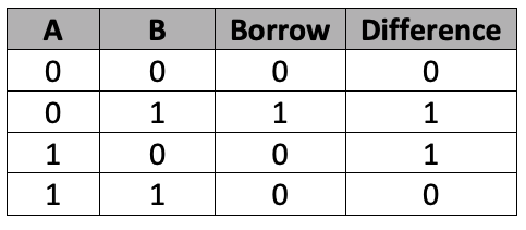
Half-subtractor circuit

Truth table

Now, let’s write, compile, and simulate a VHDL program to get a waveform output. Then, we’ll verify the waveform output with the given truth table.

Before starting, be sure to review the step-by-step procedure provided in VHDL Tutorial – 3 to properly design the project, as well as edit and compile the program and the waveform file, including the final output.

VHDL program:

library IEEE;
use IEEE.STD_LOGIC_1164.ALL;

entity half_sub is
    port ( a,b : in std_logic;
           dif,bo: out std_logic
           );
end half_sub;

architecture sub_arch of half_sub is
  begin
     dif <= a xor b;
     bo <= (not a) and b;
end sub_arch;

Note:

  • The “entity” describes the input-output connections of the digital circuit. As per the circuit given here, you’ll note that there are two inputs (‘a’ and ‘b’) and two outputs (‘dif’ and ‘bo’).
  • The “architecture” describes the operation of the circuit, which means how the output is generated from the given input.

To refresh your memory about how this works, go through the first two VHDL tutorials (1 and 2) of this series.

Next, compile the above program, creating a waveform file with all of the necessary inputs and outputs that are listed, and simulate the project. You should get the following result…

Simulation waveform

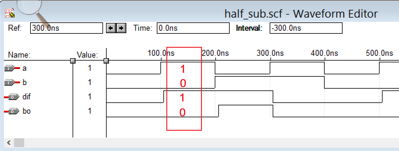
Verify the ‘dif’ and ‘bo’ output waveforms with the given truth table. For a=1 and b=0 inputs, the outputs are bo=0 and dif=1, which are highlighted in image.

Next, let’s move onto the full-subtractor circuit and its design.

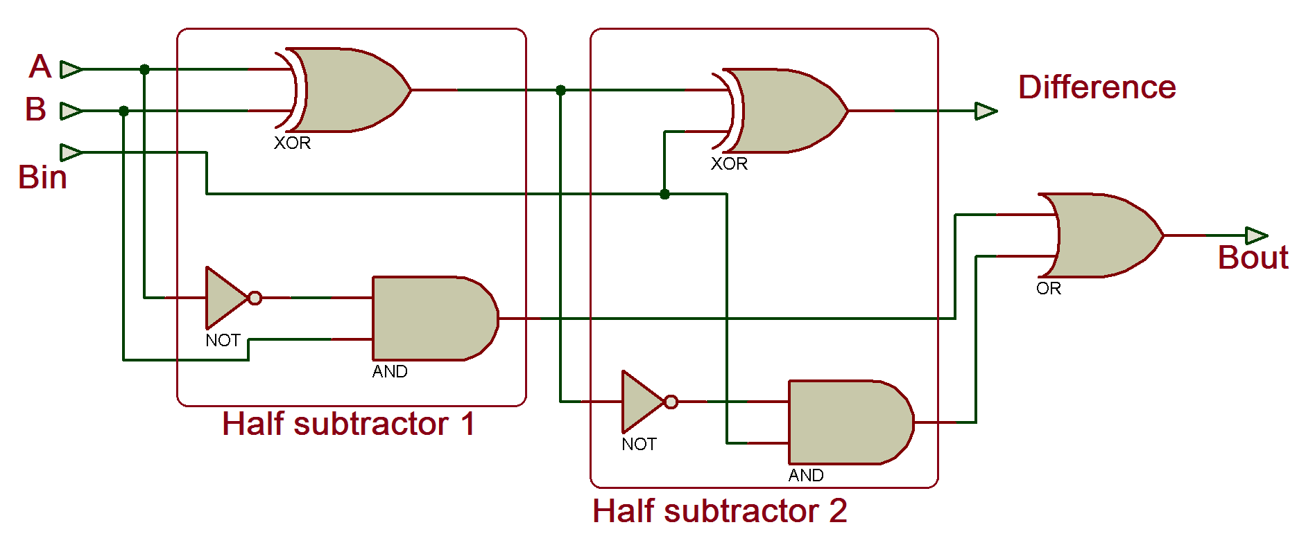
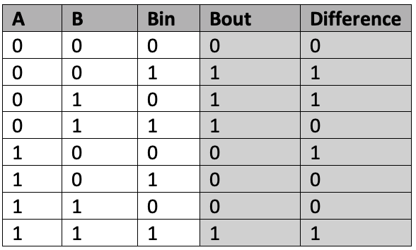
Full subtractor circuit

Truth table

Let’s write the VHDL program for this circuit. In previous tutorial, we designed the full-adder circuit using a structural-modeling style for the VHDL programming. We’ll use the same modeling style to design the full subtractor.

We’ll build the full subtractor circuit by using the half-subtractor circuit and the “OR gate” as components (or blocks). In the circuit diagram you can see the full-subtractor circuit consist of two half-adder and an OR gate.

VHDL program

library IEEE;
Use IEEE. STD_LOGIC_1164.all;
entity full_sub IS
port (a,b,bin :in STD_LOGIC;
      dif,bout : out STD_LOGIC);
end full_sub;

———————–architecture of full subtractor————-

architecture FS_arch of full_sub is

—————————–half adder component————————–

component half_sub is
port (p,q :in STD_LOGIC;
      dif,bo: out STD_LOGIC);
end component;

———————or gate component————————-

component or_gate is
port (p1,q1 :in STD_LOGIC;
      r1: out STD_LOGIC);
end component;

——————————-

signal d1,b1,b2 : STD_LOGIC;
begin
 w1: half_sub port map (a,b,d1,b1);
 w2: half_sub port map (d1,bin,dif,b2);
 w3: or_gate port map (b1,b2,bout);
end FS_arch;

————————– half subtractor program ————————

library IEEE;
Use IEEE. STD_LOGIC_1164.all;

entity half_sub is
      port (p,q : in STD_LOGIC;
      dif,bo : out STD_LOGIC);
end half_sub;
architecture HS_arch of half_sub IS
 begin
      dif <=  p xor q;
      bo <= (not p) and q;
end HS_arch;

—————————–or gate program——————————

library IEEE;
Use IEEE. STD_LOGIC_1164.all;

entity or_gate is
      port (p1,q1:in STD_LOGIC;
      r1: out STD_LOGIC);
end or_gate;
architecture or_g of or_gate IS
 begin
      r1 <= p1 or q1;
end or_g;

To compile the above program:

  • Create the waveform file with all of the inputs and outputs listed
  • Apply the different input combinations
  • Save the waveform file and simulate the project

You should get this result…

Simulation waveforms

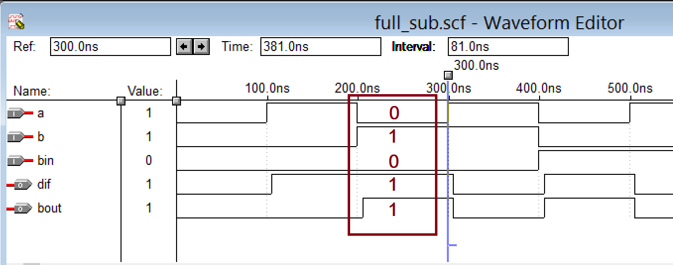
Compare the outputs of the ‘dif’ and ‘bout’ with the given truth table. In the above diagram, one case is highlighted as a=0, b=1, and bin=0 with the outputs of dif=1 and bout=1.

In the next tutorial, we’ll learn how to design an 8-bit parity generator and parity checker circuits by using the VHDL.


Filed Under: Tutorials, VHDL


Questions related to this article?
👉Ask and discuss on Electro-Tech-Online.com and EDAboard.com forums.


Tell Us What You Think!! Cancel reply

You must be logged in to post a comment.

HAVE A QUESTION?

Have a technical question about an article or other engineering questions? Check out our engineering forums EDABoard.com and Electro-Tech-Online.com where you can get those questions asked and answered by your peers!


Featured Tutorials

  • Designing Gate Driver Circuit and Switching Mechanism for Modified Sine Wave Inverter – (Part 9/17)
  • Completing Modified Sine Wave Inverter Design with Full Bridge Circuit and Step Up Transformer – (Part 10/17)
  • Designing an Offline UPS – Part (12 /17)
  • How to reduce Switching Time of a Relay – (Part 15/17)
  • Testing MOSFET – (Part 16/17)
  • Driving High Side MOSFET using Bootstrap Circuitry – (Part 17/17)

Stay Up To Date

Newsletter Signup

Sign up and receive our weekly newsletter for latest Tech articles, Electronics Projects, Tutorial series and other insightful tech content.

EE Training Center Classrooms

EE Classrooms

Recent Articles

  • Infineon offers DC-DC controller for full LED headlamps without a microcontroller
  • Vishay launches new high-precision, thin-film wraparound chip resistor
  • STMicroelectronics’ common-mode filters ensure signal integrity in serial interfaces
  • Renesas’ RA Family microcontrollers earn CAVP certification for cryptographic algorithms
  • MicroPython: Serial data communication in ESP8266 and ESP32 using UART

Most Popular

5G 555 timer circuit 8051 ai Arduino atmega16 automotive avr dc motor display Electronic Part Electronic Parts Fujitsu ic infineontechnologies integratedcircuit Intel IoT ir lcd ldr led maximintegratedproducts microchip microchiptechnology Microchip Technology microcontroller microcontrollers mosfet motor powermanagement Raspberry Pi remote renesaselectronics Research robot samsung semiconductor sensor software STMicroelectronics switch Technology vishayintertechnology wireless

RSS EDABOARD.com Discussions

  • PS4 chip replacement not going to plan
  • Voltage reference level - how to choose?
  • Boost converter, 3W...shielded or unshielded inductor?
  • What is the function of the long stub?
  • HV Relays - Power Capacity

RSS Electro-Tech-Online.com Discussions

  • SPI Questions
  • Dog Scarer
  • Unusual phenomenon
  • Audio equalizer
  • Background of Members Here
Engineers Garage
  • Analog IC TIps
  • Connector Tips
  • DesignFast
  • EDABoard Forums
  • EE World Online
  • Electro-Tech-Online Forums
  • Microcontroller Tips
  • Power Electronic Tips
  • Sensor Tips
  • Test and Measurement Tips
  • 5G Technology World
  • About Us
  • Contact Us
  • Advertise

Copyright © 2022 WTWH Media LLC. All Rights Reserved. The material on this site may not be reproduced, distributed, transmitted, cached or otherwise used, except with the prior written permission of WTWH Media
Privacy Policy | Advertising | About Us

Search Engineers Garage

  • Projects and Tutorials
    • Electronic Projects
      • 8051
      • Arduino
      • ARM
      • AVR
      • PIC
      • Raspberry pi
      • STM32
    • Tutorials
    • Circuit Design
    • Project Videos
    • Components
  • Articles
    • Tech Articles
    • Insight
    • Invention Stories
    • How to
    • What Is
  • News
    • Electronic Products News
    • DIY Reviews
    • Guest Post
  • Forums
    • EDABoard.com
    • Electro-Tech-Online
    • EG Forum Archive
  • Digi-Key Store
    • Cables, Wires
    • Connectors, Interconnect
    • Discrete
    • Electromechanical
    • Embedded Computers
    • Enclosures, Hardware, Office
    • Integrated Circuits (ICs)
    • Isolators
    • LED/Optoelectronics
    • Passive
    • Power, Circuit Protection
    • Programmers
    • RF, Wireless
    • Semiconductors
    • Sensors, Transducers
    • Test Products
    • Tools
  • EE Resources
    • DesignFast
    • LEAP Awards
    • Oscilloscope Product Finder
    • White Papers
    • Webinars
  • EE Learning Center
  • Women in Engineering