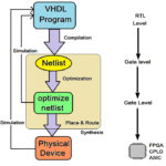
In the previous tutorial on the basics of VHSlC Hardware Description Language or VHDL, we discussed the VHDL design flow and program structure. Now, it’s time to learn about the VHDL programs.
However, please note, the prerequisite for VHDL programming are the fundamentals of digital electronics and digital circuit design. To fully understand these programs, it’s important that you first have adequate knowledge of Boolean algebra, logic gates, combinational and sequential logic circuits, etc.
Before you start here, consider giving yourself a quick refresher on the fundamentals of digital electronics.
Let’s begin with some standard and easy VHDL programs…
The full adder VHDL program:
library IEEE;
use IEEE.STD_LOGIC_1164.ALL;
entity full_adder is
port ( a, b, cin : IN STD_LOGIC;
sum, cout : OUT STD_LOGIC);
end full_adder;
architecture full_adder_arch of full_adder is
begin
sum <= a xor b xor cin;
cout <= (a and b) or (b and cin) or (a and cin);
end full_adder_arch;
The 2-to-4 decoder VHDL program:
library IEEE;
use IEEE.STD_LOGIC_1164.ALL;
entity decoder2x4 is
port ( a, b, : IN STD_LOGIC;
o0,o1,o2,o3 : OUT STD_LOGIC);
end decoder2x4;
architecture decoder_arch of decoder2x4 is
begin
o0 <= (not a) and (not b);
o1 <= a and (not b);
o2 <= (not a) and b;
o3 <= a and b;
end decoder_arch;
The Binary-to-Gray code converter VHDL program:
library IEEE;
use IEEE.STD_LOGIC_1164.ALL;
entity BtoG is
port ( B0,B1,B2,B3 : IN STD_LOGIC;
G0,G1,G2,G3 : OUT STD_LOGIC);
end BtoG;
architecture BtoG_arch of BtoG is
begin
G3 <= B3;
G2 <= B3 xor B2;
G1 <= B2 xor B1;
G0 <= B1 xor B0;
end decoder_arch;
The 4-bit parity generator VHDL program:
library IEEE;
use IEEE.STD_LOGIC_1164.ALL;
entity parity_gen is
port ( B0,B1,B2,B3 : IN STD_LOGIC;
p : OUT STD_LOGIC);
end parity_gen;
architecture parity_gen_arch of parity_gen is
begin
p <= B0 xor (B1 xor (B2 xor B3));
end parity_gen_arch;
The above programs present the dataflow modeling style that’s typically used for combinational logic circuits. To write a program for the sequential logic circuit, it’s better to use the behavioral modeling style.
Here are a few examples of VHDL programs that use the behavioral modeling style.
The 4×1 multiplexer VHDL program:
library ieee;
use ieee.std_logic_1164.all;
entity mux41 is
port ( d : in std_logic_vector (0 to 3);
s : in std_logic_vector (0 to 1);
o : out std_logic);
end mux41;
architecture mux41_arch of mux41 is
begin
process (d,s)
begin
case s is
when “00” => o<= d(0);
when “01” => o<= d(1);
when “10” => o<= d(2);
when “11” => o<= d(3);
end case;
end process;
end mux41_arch;
The D flip-flop (with active high reset input) VHDL program:
library ieee;
use ieee.std_logic_1164.all;
entity flip_flop is
port (clk,Din,rst : in std_logic;
Q: out std_logic;
Qnot : out std_logic);
end flip_flop;
architecture my_flipflop of flip_flop is
begin
process (clk,Din,rst)
begin
if(rst=’1′) then
Q <=’0′;
Qnot <=’1′;
elsif(clk’event and clk=’1′) then
Q <= Din;
Qnot <= not Din;
end if;
end process;
end my_flipflop;
The 4-bit binary counter VHDL program:
library IEEE;
use IEEE.STD_LOGIC_1164.ALL;
use IEEE.STD_LOGIC_ARITH.all;
use IEEE.STD_LOGIC_UNSIGNED.all;
entity counter is
Port ( rst,clk : in std_logic;
o: out std_logic_vector(0 to 3));
end counter;
architecture counter_arch of counter is
signal count : std_logic_vector(0 to 3);
begin
process(rst,clk)
begin
if (rst = ‘1’) then count <= “0000”;
elsif (clk’event and clk = ‘1’) then count <= count + 1;
end if;
end process;
o <= count;
end counter_arch;
If the circuit is small and simple, it’s possible to use the above two modeling styles for the VHDL program. However, if the circuit is large and complex, it’s necessary to use the structural modeling style.
In this style, a large circuit is considered an interconnection of smaller components. This is because the complete circuit is represented by a set of interconnected components.
Here’s an example of a VHDL program that employs the structural modeling style.
The full adder circuit using the half adder and OR the gate as components:
library IEEE;
Use IEEE. STD_LOGIC_1164.all;
entity fulladder IS
port (a,b,cin :in STD_LOGIC;
sum,carry : out STD_LOGIC);
end fulladder;
——————————architecture of full adder
architecture FA_arch of fulladder is
—————————–half adder component
component half_adder is
port (p,q :in STD_LOGIC;
s,cy: out STD_LOGIC);
end component;
—————————————or gate component
component or_gate is
port (p1,q1 :in STD_LOGIC;
r1: out STD_LOGIC);
end component;
——————————-
signal s1,c1,c2 : STD_LOGIC;
begin
w1: half_adder port map (a,b,s1,c1);
w2: half_adder port map (s1,cin,sum,c2);
w3: or_gate port map (c1,c2,carry);
end FA_arch;
————————— half adder component program
entity half_adder is
port (p,q : in STD_LOGIC;
s,cy : out STD_LOGIC);
end half_adder;
architecture HA_arch of half_adder IS
begin
s <= p xor q;
cy <= p and q;
end HA_arch;
—————————-or gate component program
entity or_gate is
port (p1,q1:in STD_LOGIC;
r1: out STD_LOGIC);
end or_gate;
architecture or_gate_arch of or_gate IS
begin
r1 <= p1 or q1;
end or_gate_arch;
To get a better understanding of the three modeling styles, let’s design a 2-to-4 decoder using all three methods.
The 2-to-4 decoder using the dataflow modeling style (this is same as before):
library IEEE;
use IEEE.STD_LOGIC_1164.ALL;
entity decoder2x4 is
port ( a, b, : IN STD_LOGIC;
o0,o1,o2,o3 : OUT STD_LOGIC);
end decoder2x4;
architecture decoder_arch of decoder2x4 is
begin
o0 <= (not a) and (not b);
o1 <= a and (not b);
o2 <= (not a) and b;
o3 <= a and b;
end decoder_arch;
The 2-to-4 decoder using the behavior modeling style:
library IEEE;
use IEEE.STD_LOGIC_1164.ALL;
entity decoder2x4 is
port ( I : IN STD_LOGIC_VECTOR(0 to 1);
O : OUT STD_LOGIC_VECTOR (0 to 3));
end decoder2x4;
architecture decoder_arch of decoder2x4 is
begin
process(I)
begin
case I is
when “00” => O <= “0001”;
when “01” => O <= “0010”;
when “10” => O <= “0100”;
when “11” => O <= “1000”;
end case;
end process;
end decoder_arch;
The 2-to-4 decoder using the structural modeling style:
library IEEE;
use IEEE.STD_LOGIC_1164.ALL;
entity decoder2x4 is
port ( I : IN STD_LOGIC_VECTOR(0 to 1);
O : OUT STD_LOGIC_VECTOR (0 to 3));
end decoder2x4;
architecture decoder_arch of decoder2x4 is
——————— AND GATE component———————-
component and_gate is
port( a, b : in STD_LOGIC;
y : out STD_LOGIC);
end component;
——————- NOT GATE component ———————–
component not_gate is
port( m : in STD_LOGIC;
n : out STD_LOGIC);
end component;
—————– intermediate output signals—————–
signal p,q : STD_LOGIC;
—————- component port mapping ———————-
begin
w1: not_gate port map (I(0),p);
w2: not_gate port map (I(1),q);
w3: and_gate port map (p,q,O(0));
w4: and_gate port map (I(0),q,O(1));
w5: and_gate port map (p,I(1),O(2));
w3: and_gate port map (I(0),I(1),O(3));
end decoder_arch;
——————— AND GATE component program————–
entity and_gate is
port( a, b : in STD_LOGIC;
y : out STD_LOGIC);
end and_gate;
architecture and_gate_arch of and_gate is
begin
y <= a and b;
end and_gate_arch;
——————- NOT GATE component program—————-
entity not_gate is
port( m : in STD_LOGIC;
n : out STD_LOGIC);
end not_gate;
architecture not_gate_arch of not_gate is
begin
n <= not m;
end not_gate_arch;
As you can see, we can design any digital circuit using any of the modeling styles. It’s up to the designer to choose the ideal and most suitable modeling style to describe the circuit
In the next tutorial, we’ll describe how to compile, simulate, execute, and verify these VHDL programs when using the MAX+II software tool (from Altera).
You may also like:


Filed Under: Tutorials, VHDL, VHDL

Questions related to this article?
👉Ask and discuss on Electro-Tech-Online.com and EDAboard.com forums.
Tell Us What You Think!!
You must be logged in to post a comment.