In the previous two tutorials, we learned about VHDL basics and programs. Next, we’ll simulate and verify the VHDL programs.
To edit, compile, execute (simulate), or verify a VHDL program, there are requirements including software tools, such as:
- ISE from XILINX
- ModelSim from Mentor Graphics
- Riviera from Aldec
- Quartus-II from Altera etc.
All of these are commercial simulators. Here, we are going to use Altera’s MAX+II VHDL simulator, which is designed for educators and students.
To begin, follow the step-by-step procedure to build and simulate the VHDL program for any digital circuit using MAX+II.
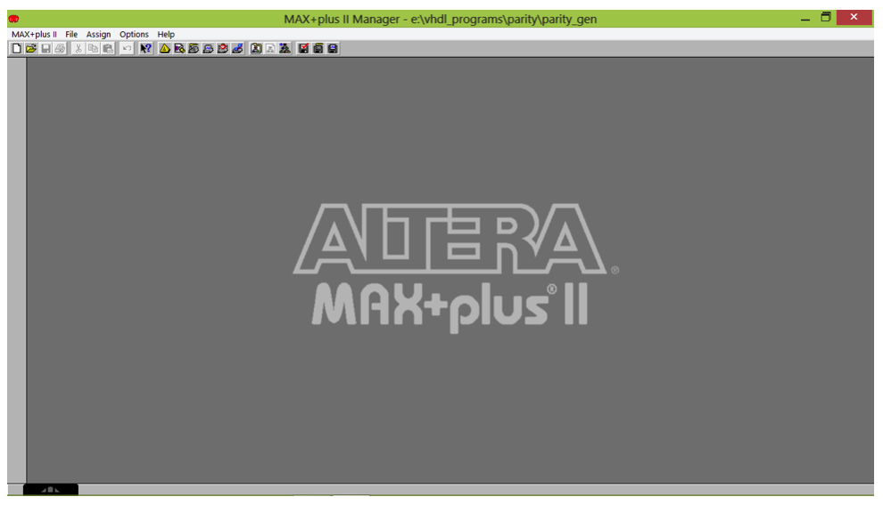
Step 1
Open MAX+II software from the start menu. The following screen will appear on your computer screen:
Step 2:
Create a new file from the file menu -> new. A new dialog box will open. From here, select the text editor file and click OK.
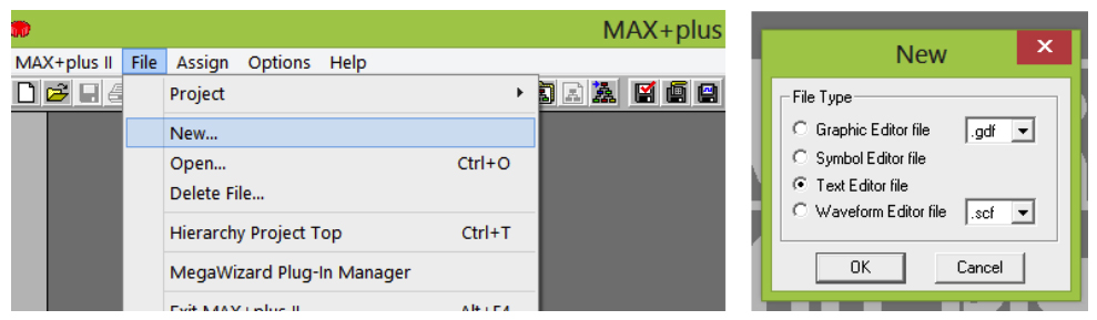
This will open the text editor in which you can write the VHDL program.
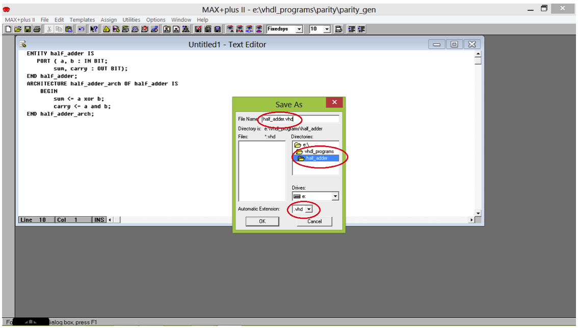
Step 3:
Let’s start with the simple program of half adder. Write the following code in the editor area and click save.
ENTITY half_adder IS
PORT ( a, b : IN BIT;
sum, carry : OUT BIT);
END half_adder;
ARCHITECTURE half_adder_arch OF half_adder IS
BEGIN
sum <= a xor b;
carry <= a and b;
END half_adder_arch;
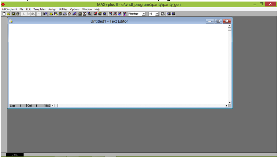
Step 4:
Save the program file by clicking the save button (or file menu – > save). The save dialog box will appear. Select the proper directory and folder (for example, here it is: E:\vhdl_programs\half_adder)
Note: it’s advisable to create a new folder for every new VHDL program in the directory. Also, there should NOT be any space (“ “) in the complete path for the VHDL program.
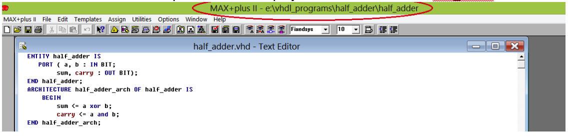
Give the file the same name as the entity name, “half_adder” and select the .vhd extension as per this screenshot.
After you’ve saved your work, you’ll see that all of the keywords, such as “ENTITY”, “IS”, “ARCHITECTURE”, etc. are all highlighted.
Step 5:
Next, you will have to set this project to an active one. To do so, go to file – > project – > set project to current file.
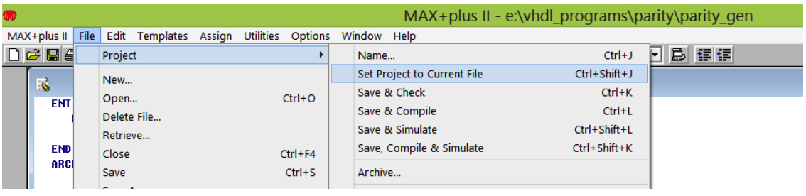
You will notice that the MAX + plus II will set the project to the current file as half_adder.
Step 6:
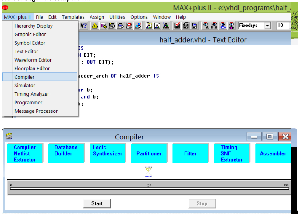
Now compile the file from the MAX+PLUS II – > compiler. The compiler will appear on the screen. Press start to begin the compilation.
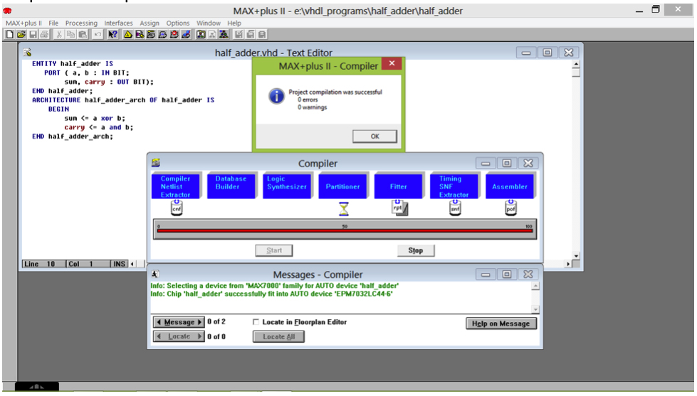
When the compilation is complete, it should indicator 0 errors and 0 warnings. Simply click OK to complete the compilation.
Step 7:
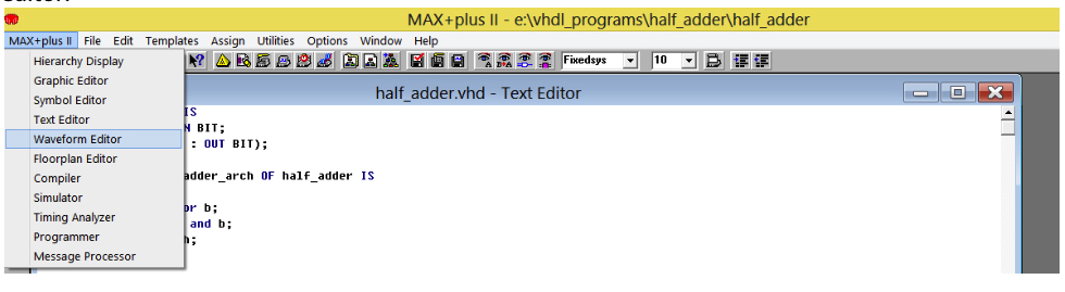
Now we have to create one more file that’s a waveform editor file, which will provide us with the results as input-output waveforms. To create the waveform editor file, go to MAX+II – > waveform editor.
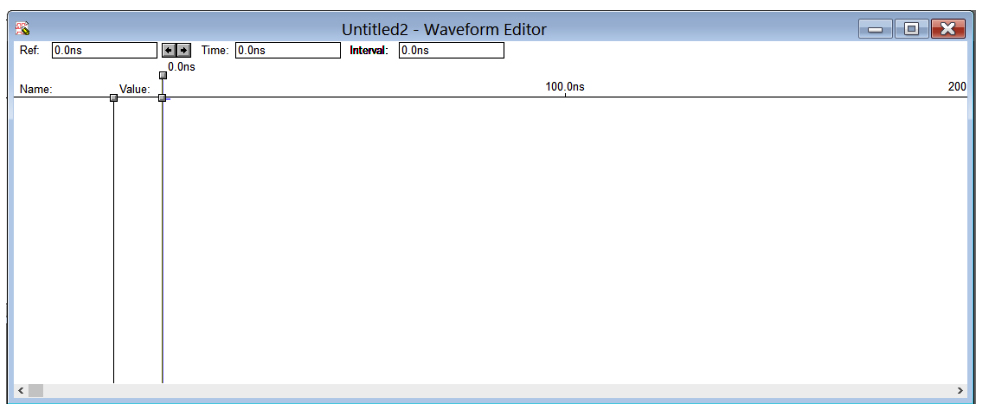
It will open the following waveform editor window:
Step 8:
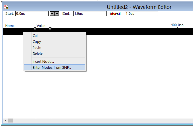
Right-click on the blank area. Then, from the pop-up menu, select the “enter node from SNF”.
The new dialog box will appear. First, select “list” and then the ‘=>’ button before clicking OK.
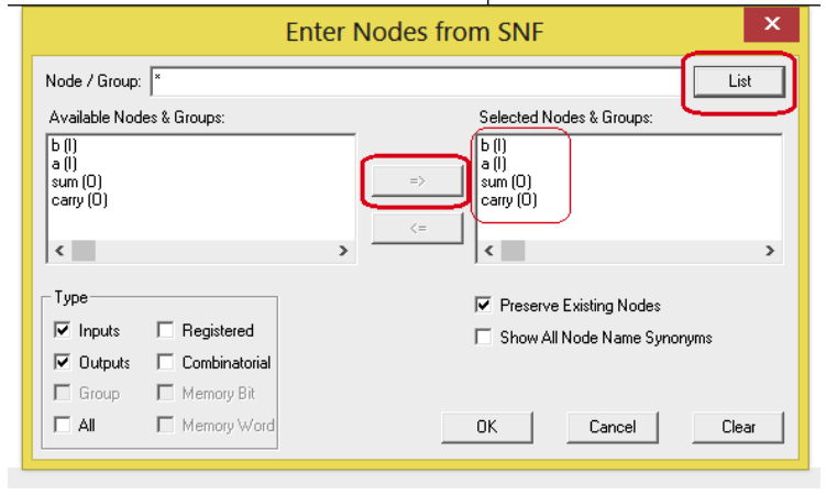
You will see all of the input-output signal waveforms. The ‘a’, ‘b’, ‘sum’ and ‘carry’ will appear on the waveform editor window similar to this image.
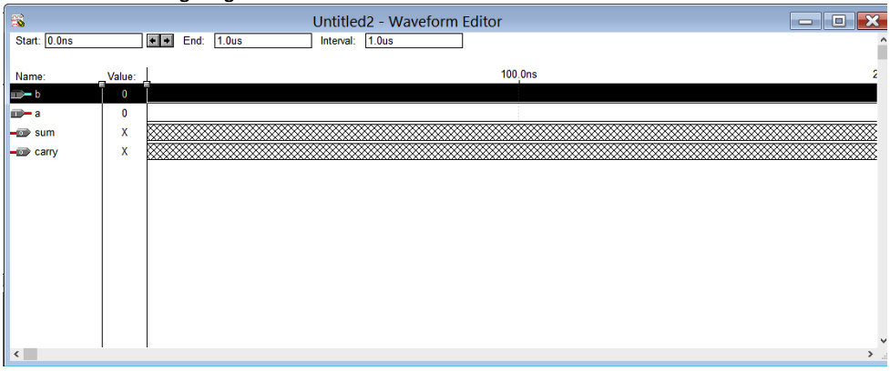
Here, the ‘xx’ lines indicate the output signals that you cannot edit. But you can edit the ‘a’ and ‘b’ input signals.
Step 9:
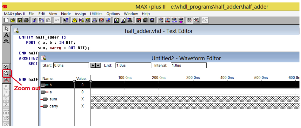
Next, zoom out of the waveform by pressing the zoom out button on the left-hand side of the screen.
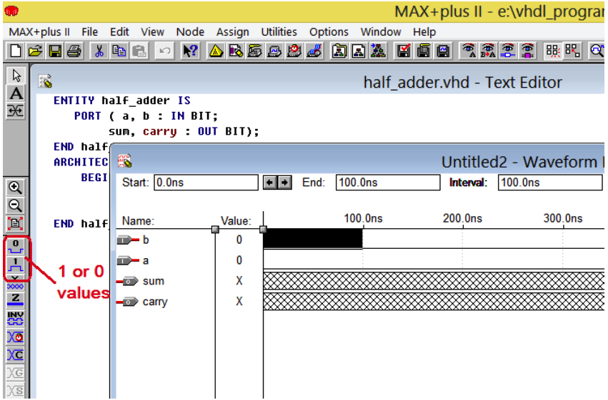
Now enter the values of ‘a’ and ‘b’ as ‘1’ and ‘0’ by selecting the area (simply press and hold the mouse button down to select the area). Be sure to select the value 1 or 0 from the left-hand side.
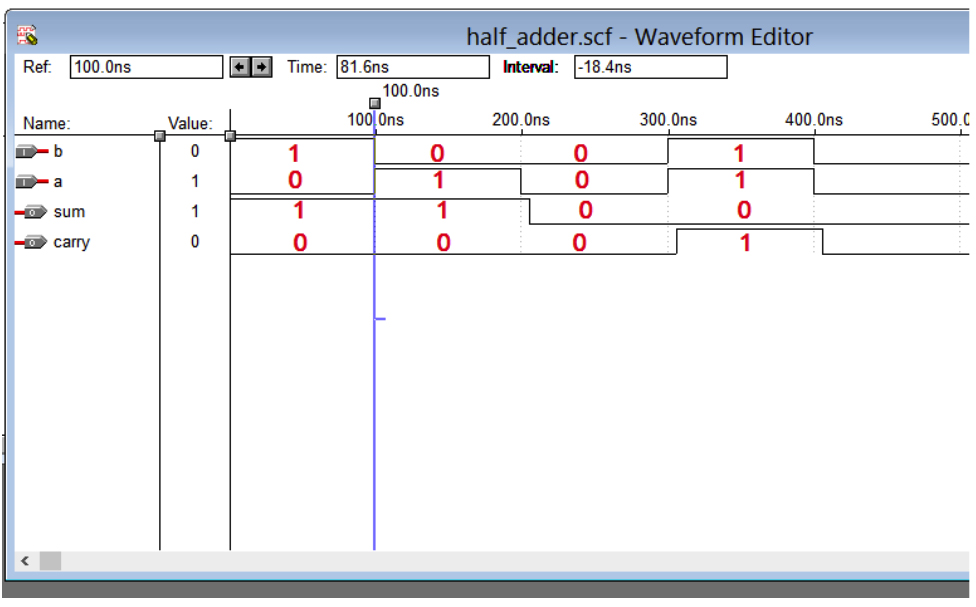
Set the 1 or 0 values of ‘a’ and ‘b’ as you wish. Make all four of the combinations 00, 01, 10, and 11 as shown here:
Step 10:
Save the waveform file. By default, its name will be “half_adder.swf”. Click OK.
Step 11:
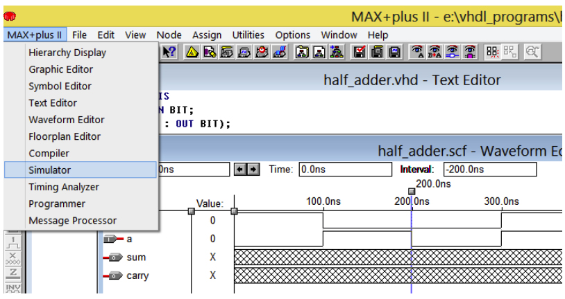
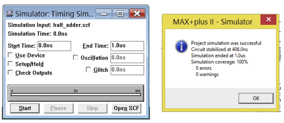
Next, go to the MAX+II – > simulator to simulate the work here.
Click start on the simulator dialogue box. When the simulation is successful, the dialogue box will appear as 0 errors and 0 warnings.
Step 12:
Click OK and open the wavefrom editor file to verify the result of the half adder.
This procedure must be followed to edit, compile, simulate, and verify all of the VHDL programs.
The next tutorial will deal with the simulation of different digital circuits in the VHDL when using MAX + II.
You may also like:


Filed Under: Tutorials, VHDL, VHDL

Questions related to this article?
👉Ask and discuss on EDAboard.com and Electro-Tech-Online.com forums.
Tell Us What You Think!!
You must be logged in to post a comment.