Note: it’s recommended to follow this VHDL tutorial series in order, starting with the first tutorial.
In previous tutorials VHDL tutorial – 8, we learned how to build different gates (such as AND, OR, NOR, NOT, etc.) by only using the NOR gate in VHDL. We were able to successfully prove that he NOR gate is universal.
In this tutorial, we will learn how to:
- Write a VHDL program that can build a digital circuit from a given Boolean equation.
- Verify the output waveform of the program (digital circuit) with the truth table of the Boolean equation.
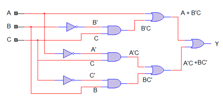
1. The Boolean equation A + B’C + A’C + BC’
Circuit
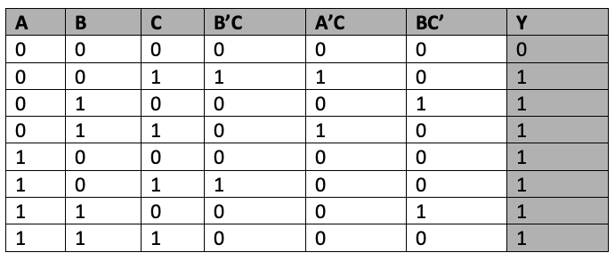
Truth table
We will write a VHDL program, compile and simulate it, and get the output in a waveform. We’ll also verify the output waveforms with the given truth table.
First, it’s important to review the step-by-step procedure provided in VHDL Tutorial – 3. In that tutorial, we learn how to design a project, edit and compile a program, create a waveform file, simulate the program, and generate the final output waveforms.
VHDL program
library IEEE;
use IEEE.STD_LOGIC_1164.ALL;
entity boolean_equ is
port ( a,b,c : in std_logic;
y: out std_logic
);
end boolean_equ;
architecture bool_equ_arch of boolean_equ is
begin
y <= a or (not(b) and c) or (not(a) and c) or (not(c) and b);
end bool_equ_arch;
Note:
- “entity” describes the input-output connections of the digital circuit. As per the circuit given above, there are three inputs: ‘a’, ‘b,’ and ‘c,’ with only one output ‘y.’
- “architecture” describes the operation of the circuit, which refers to how the output is generated from the given input.
To refresh your memory about how this works, go through the first two VHDL tutorials (1 and 2) of this series.
Next, compile the above program, creating a waveform file with all of the necessary inputs and outputs that are listed, and simulate the project.
Here are the results…
Simulation waveform
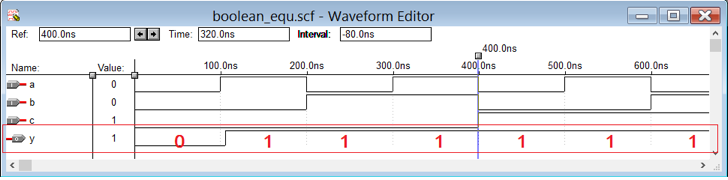
Verify that the output for ‘y’ is always 1 and for all of the conditions of the inputs (a, b, and c) except when all of the inputs are 0.
Now let’s take at another Boolean equation…
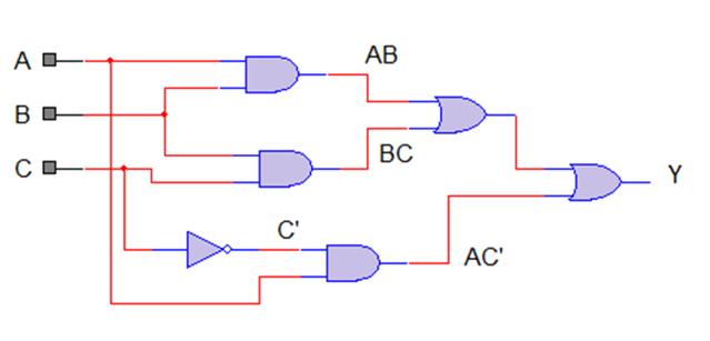
2. Boolean equation AB + AC’ + BC
Circuit
Truth table
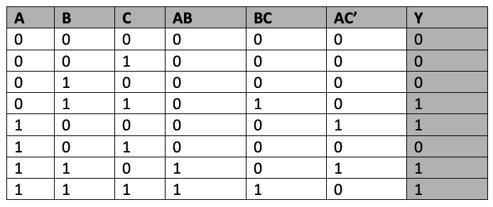
Now let’s write a VHDL program for this circuit, only this time we’ll use the structural-modeling style of the VHDL programming instead of the data-flow modeling style.
The previous program was written using the data-flow modeling style as it’s the simplest for designing circuits with VHDL and ideal for beginners. However, that style is not used for designing digital circuits using VHDL. The most widely used style for this is structural modeling because it divides complete circuits into smaller components and then integrates them to build a complete circuit.
For this reason, structural modeling is useful for big or complex digital circuits. Users can start by designing small-small blocks (components) of the complete circuit and then simply integrate all of the blocks (components) together.
Here is the VHDL program using the structural-modeling style.
VHDL program
library IEEE;
use IEEE.STD_LOGIC_1164.ALL;
entity bool_equ is
port (a,b,c :in STD_LOGIC;
y : out STD_LOGIC);
end bool_equ;
————architecture of boolean equation ckt ———–
architecture bool_equ_arch of bool_equ is
—————AND gate component ———————-
component and_gate is
port (p,q :in STD_LOGIC;
x: out STD_LOGIC);
end component;
—————–OR gate component ———————
component or_gate is
port (p1,q1 :in STD_LOGIC;
x1: out STD_LOGIC);
end component;
—————-NOT gate component ———————-
component not_gate is
port (w :in STD_LOGIC;
z: out STD_LOGIC);
end component;
———————————————————-
signal s1,s2,s3,s4,s5 : STD_LOGIC;
begin
w1: and_gate port map (a,b,s1);
w2: and_gate port map (b,c,s2);
w3: not_gate port map (c,s3);
w4: and_gate port map (a,s3,s4);
w5: or_gate port map (s1,s2,s5);
w6: or_gate port map (s4,s5,y);
end bool_equ_arch;
————– AND gate entity and architecture ————–
library IEEE;
use IEEE.STD_LOGIC_1164.ALL;
entity and_gate is
port(p,q :in STD_LOGIC;
x: out STD_LOGIC);
end and_gate;
architecture and_arch of and_gate is
begin
x<=p and q;
end and_arch;
————– OR gate entity and architecture —————
library IEEE;
use IEEE.STD_LOGIC_1164.ALL;
entity or_gate is
port(p1,q1 :in STD_LOGIC;
x1: out STD_LOGIC);
end or_gate;
architecture or_arch of or_gate is
begin
x1<=p1 or q1;
end or_arch;
————– NOT gate entity and architecture ————–
library IEEE;
use IEEE.STD_LOGIC_1164.ALL;
entity not_gate is
port(w :in STD_LOGIC;
z: out STD_LOGIC);
end not_gate;
architecture not_arch of not_gate is
begin
z <= not w;
end not_arch;
To learn more about this structural-modeling style, please refer to Tutorial 2 of this series.
Next, compile the above program – create the waveform file with all of the inputs and outputs listed, apply the different input combinations, and save the waveform file.
Simulate the project and you will get the following result:
Simulation waveform
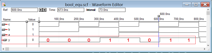
Verify the output of ‘y’ by comparing it with the truth table given. It should match with the truth table. This means that by using VHDL, we can design a digital circuit for any given Boolean equation.
In the next tutorial, we’ll learn how to design half and full adder circuits using VHDL.
You may also like:


Filed Under: Tutorials, VHDL, VHDL

Questions related to this article?
👉Ask and discuss on Electro-Tech-Online.com and EDAboard.com forums.
Tell Us What You Think!!
You must be logged in to post a comment.