Engineers Garage

  • Projects and Tutorials
    • Circuit Design
    • Electronic Projects
      • 8051
      • Arduino
      • ARM
      • AVR
      • PIC
      • Raspberry pi
      • STM32
    • Tutorials
    • Components
  • Articles
    • EG Blogs
    • Insight
    • Invention Stories
    • How to
    • What Is
    • News
      • EE Design News
      • DIY Reviews
      • Guest Post
      • Sponsored Content
  • Forums
    • EDABoard.com
    • Electro-Tech-Online
    • EG Forum Archive
  • Digi-Key Store
    • Cables, Wires
    • Connectors, Interconnect
    • Discrete
    • Electromechanical
    • Embedded Computers
    • Enclosures, Hardware, Office
    • Integrated Circuits (ICs)
    • Isolators
    • LED/Optoelectronics
    • Passive
    • Power, Circuit Protection
    • Programmers
    • RF, Wireless
    • Semiconductors
    • Sensors, Transducers
    • Test Products
    • Tools
  • EE Resources
    • DesignFast
    • LEAP Awards
    • Oscilloscope Product Finder
    • Video
    • White Papers
    • Webinars
  • EE Learning Center
  • Women in Engineering

VHDL Tutorial – 12: Designing an 8-bit parity generator and checker circuits

October 15, 2020 By Ashutosh Bhatt

Note: it’s recommended to follow this VHDL tutorial series in order, starting with the first tutorial.

In the previous tutorial VHDL tutorial – 11, we learned how to design half and full-subtractor circuits by using the VHDL.

In this tutorial, we will:

  • Write a VHDL program to build an 8-bit parity generator and checker circuits
  • Verify the output waveform of the program (as a digital circuit) with the truth table of the parity generator and parity checker circuits

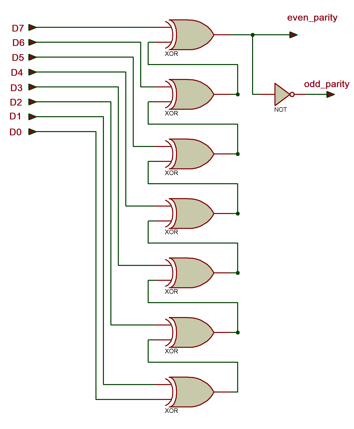
The 8-bit parity generator circuit
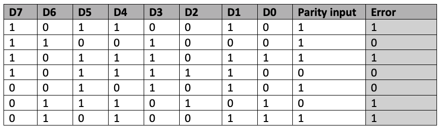
Truth table

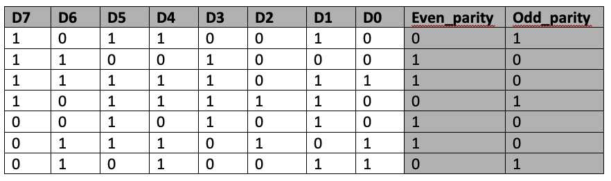
Note: here not all of the 256 combinations of the D0-D7 are displayed. Just a few are taken as examples.

Now, let’s write, compile, and simulate a VHDL program to get a waveform output. Then, we’ll verify the waveform output with the given truth table.

Before starting, be sure to review the step-by-step procedure provided in VHDL Tutorial – 3 to properly design the project, as well as edit and compile the program and the waveform file, including the final output.

VHDL program

library ieee;
use ieee.std_logic_1164.all;
entity parity is
      port( data:in bit_vector(7 downto 0);
                  even_p,odd_p: out bit);
end parity;
architecture parity_gen of parity is
signal temp : bit_vector(5 downto 0);
  begin
    temp(0)<=data(0) xor data(1);
    temp(1)<=temp(0) xor data(2);
    temp(2)<=temp(1) xor data(3);
    temp(3)<=temp(2) xor data(4);
    temp(4)<=temp(3) xor data(5);
    temp(5)<=temp(4) xor data(6);
    even_p <= temp(5) xor data(7);
    odd_p <= not(temp(5) xor data(7));
end parity_gen;

Note:

  • The “entity” describes the input-output connections of the digital circuit. As per the given circuit here, there is an 8-bit data input of ‘d0-d7’ and two outputs of ‘even_p’ and ‘odd_p.’
  • The “architecture” describes the operation of the circuit, which means how the output is generated from the given input.

To refresh your memory about how this works, go through the first two VHDL tutorials (1 and 2) of this series.

Next, compile the above program, creating a waveform file with all of the necessary inputs and outputs that are listed, and simulate the project. You should get the following result…

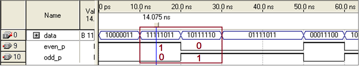
Verify the ‘even_p’ and ‘odd_p’ output waveforms with the input data of ‘D0-D7.’ For example, as highlighted in the diagram, for the input “1111 1011,” the even_p output is ‘1’ and the odd _p output is ‘0.’ For the input “1011 1110,” the even_p output is ‘0’ and the odd_p output is ‘1.’

Now, let’s build the 8-bit parity checker circuit.

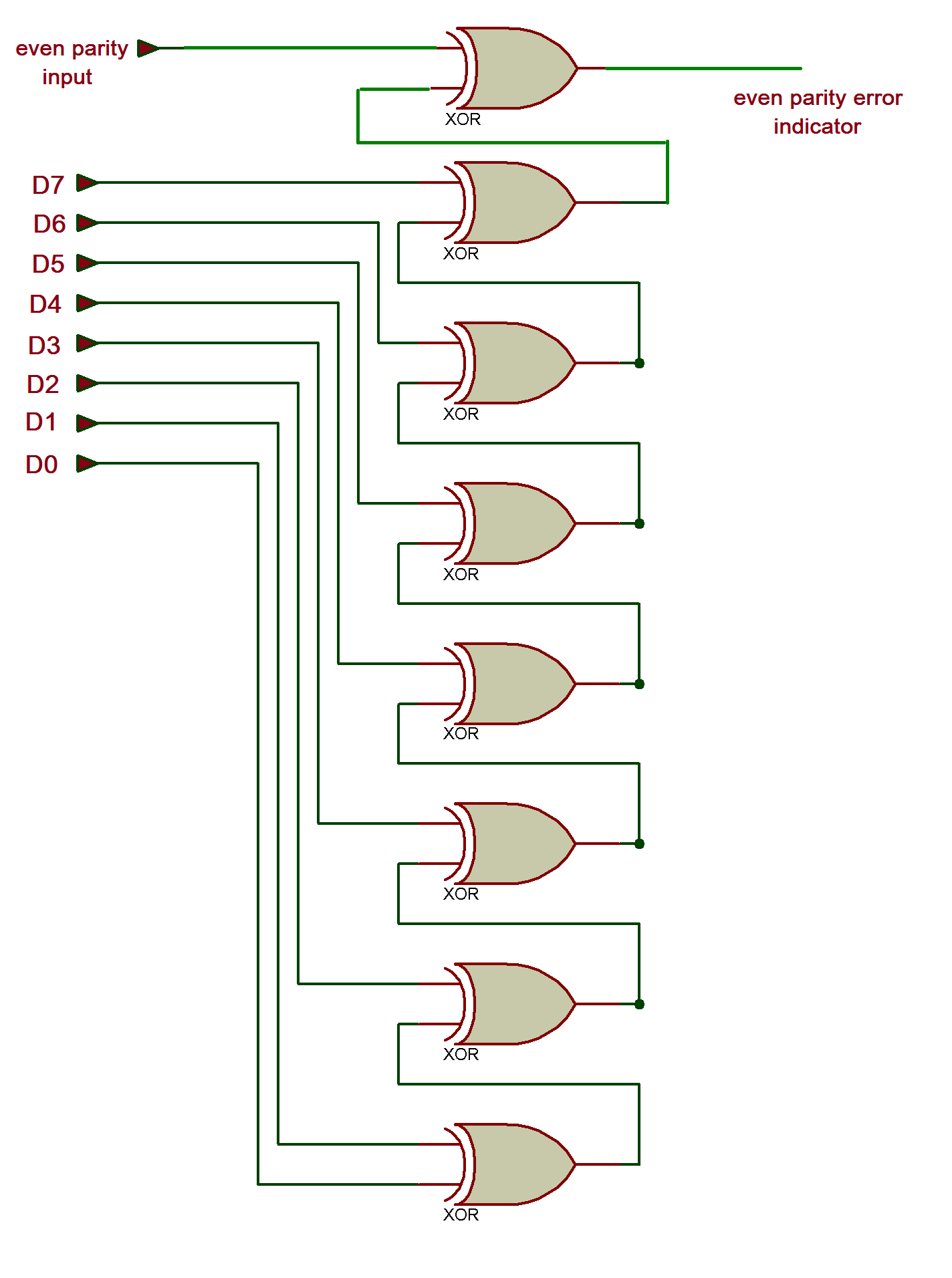
The 8-bit parity checker circuit

Truth table

VHDL program

library ieee;
use ieee.std_logic_1164.all;
entity parity_chk is
      port( data:in bit_vector(7 downto 0);
                  p: in bit;
                  e: out bit);
end parity_chk;
architecture parity_arch of parity_chk is
signal temp : bit_vector(6 downto 0);
  begin
    temp(0)<=data(0) xor data(1);
    temp(1)<=temp(0) xor data(2);
    temp(2)<=temp(1) xor data(3);
    temp(3)<=temp(2) xor data(4);
    temp(4)<=temp(3) xor data(5);
    temp(5)<=temp(4) xor data(6);
    temp(6) <= temp(5) xor data(7);
    e <= p xor temp(6);
end parity_arch;

Simulation waveforms

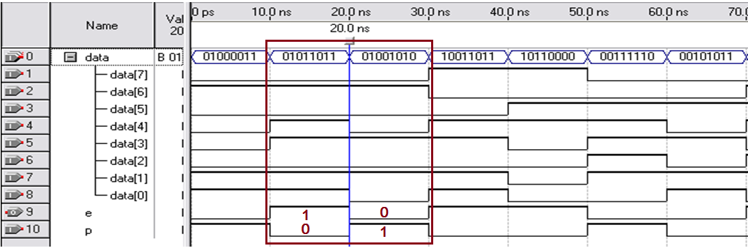
Verify the ‘e’ output waveform with the parity input of ‘p’ and the data ‘D0-D7.’ For example, as highlighted in the diagram, for the input “0101 1011” and the parity ‘1,’ the error output is ‘1.’ For the input of “0100 1010” and the parity ‘0,’ the output is ‘0.’

In the next tutorial, we’ll learn how to design 8×3 encoder and 3×8 decoder circuits using the VHDL.


Related Articles Read More >

VHDL Tutorial – 19: Designing a 4-bit binary counter using VHDL
VHDL Tutorial 18: Design a T flip-flop (with enable and an active high reset input) using VHDL
VHDL Tutorial 17: Design a JK flip-flop (with preset and clear) using VHDL
VHDL Tutorial 16: Design a D flip-flop using VHDL

Featured Tutorials

  • Screenshot of Raspbian OS on Raspberry Pi RPi Python Programming 03: Raspberry Pi as Linux System
  • Raspberry Pi Models RPI Python Programming 02: Raspberry Pi Models
  • Raspberry Pi 4 RPi Python Programming 01: Introduction to Raspberry Pi 4
  • RPi Python Programming 05: Introduction to Python
  • RPi Python programming 04 RPi Python programming 04: Setting up Raspberry Pi Linux computer
  • Python Basics RPi Python Programming 06: Python basics

Stay Up To Date

Newsletter Signup

EE Training Center Classrooms

“ee

“ee

“ee

“ee

Recent Articles

  • Arduino’s L293D motor driver shield guide
  • NXP launches its first Wi-Fi 6E Tri-Band system-on-chip
  • Nexperia launches industry’s first 80 V RETs for high-voltage bus circuits
  • TDK releases low-profile medical sensors
  • Getting started with Raspberry Pi
...

RSS EDABOARD.com Discussions

  • hysteresis variation mc sim
  • Need help with Audio intercom design circuit?
  • complex bjt transfer function amplifier
  • Creepage distance from primary to secondary of offline SMPS
  • FT232 > Package

RSS Electro-Tech-Online.com Discussions

  • new to Ardunio but trying to compile
  • Engine Temperature using an AD590 on the Oil Pressure Wire to the engine
  • Dead Battery circuits.
  • electrolytic capacitor depolarizes
  • Symphonic TV/VCR problems (potentially loose yoke)...
Engineers Garage
  • Analog IC TIps
  • Connector Tips
  • DesignFast
  • EDABoard Forums
  • EE World Online
  • Electro-Tech-Online Forums
  • Microcontroller Tips
  • Power Electronic Tips
  • Sensor Tips
  • Test and Measurement Tips
  • 5G Technology World
  • About Us
  • Contact Us
  • Advertise

Copyright © 2021 WTWH Media LLC. All Rights Reserved. The material on this site may not be reproduced, distributed, transmitted, cached or otherwise used, except with the prior written permission of WTWH Media
Privacy Policy | Advertising | About Us

Search Engineers Garage

  • Projects and Tutorials
    • Circuit Design
    • Electronic Projects
      • 8051
      • Arduino
      • ARM
      • AVR
      • PIC
      • Raspberry pi
      • STM32
    • Tutorials
    • Components
  • Articles
    • EG Blogs
    • Insight
    • Invention Stories
    • How to
    • What Is
    • News
      • EE Design News
      • DIY Reviews
      • Guest Post
      • Sponsored Content
  • Forums
    • EDABoard.com
    • Electro-Tech-Online
    • EG Forum Archive
  • Digi-Key Store
    • Cables, Wires
    • Connectors, Interconnect
    • Discrete
    • Electromechanical
    • Embedded Computers
    • Enclosures, Hardware, Office
    • Integrated Circuits (ICs)
    • Isolators
    • LED/Optoelectronics
    • Passive
    • Power, Circuit Protection
    • Programmers
    • RF, Wireless
    • Semiconductors
    • Sensors, Transducers
    • Test Products
    • Tools
  • EE Resources
    • DesignFast
    • LEAP Awards
    • Oscilloscope Product Finder
    • Video
    • White Papers
    • Webinars
  • EE Learning Center
  • Women in Engineering