Engineers Garage

  • Projects and Tutorials
    • Circuit Design
    • Electronic Projects
      • 8051
      • Arduino
      • ARM
      • AVR
      • PIC
      • Raspberry pi
      • STM32
    • Tutorials
    • Components
  • Articles
    • Tech Articles
    • Insight
    • Invention Stories
    • How to
    • What Is
  • News
    • EE Design News
    • DIY Reviews
    • Guest Post
    • Sponsored Content
  • Forums
    • EDABoard.com
    • Electro-Tech-Online
    • EG Forum Archive
  • Digi-Key Store
    • Cables, Wires
    • Connectors, Interconnect
    • Discrete
    • Electromechanical
    • Embedded Computers
    • Enclosures, Hardware, Office
    • Integrated Circuits (ICs)
    • Isolators
    • LED/Optoelectronics
    • Passive
    • Power, Circuit Protection
    • Programmers
    • RF, Wireless
    • Semiconductors
    • Sensors, Transducers
    • Test Products
    • Tools
  • EE Resources
    • DesignFast
    • LEAP Awards
    • Oscilloscope Product Finder
    • Video
    • White Papers
    • Webinars
  • EE Learning Center
  • Women in Engineering

VHDL Tutorial – 4: design, simulate and verify all digital GATE (AND, OR, NOT, NAND, NOR, XOR & XNOR) in VHDL

February 15, 2021 By Ashutosh Bhatt

In previous tutorial VHDL tutorial  3, we have learned how to design, simulate, and verify any digital circuit in VHDL using Altera’s MAX+II VHDL simulator software.

(If you are not following this VHDL tutorial series one by one, you are requested to go through all previous tutorials of these series before going ahead in this tutorial)

In this tutorial,

  • We shall write a VHDL program to build all digital gates
  • Simulate the program to design digital circuit for all gates
  • Verify the output waveform of program (digital circuit) with truth table of these logic GATES

Let us start with the digital circuit for which we shall write a VHDL program

Digital Circuit
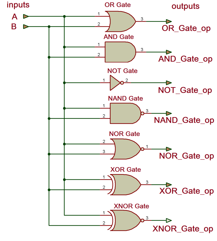
Here is the truth table for the above circuit.
Truth Table
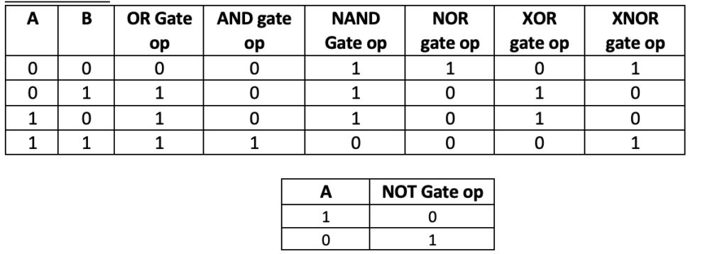
Now we shall write a VHDL program, compile it, simulate it, and get the output in the form of the waveform. Finely, we shall verify those output waveforms with the given truth table.

(Please go through step by step procedure given in previous tutorial (VHDL Tutorial 2) to create a project, edit and compile a program, create waveform file, simulate the program and generate output waveforms.)

VHDL Program
library IEEE;

use IEEE.STD_LOGIC_1164.ALL;

entity logic_gate is
     Port ( A,B : in std_logic;
               y_and,y_or,y_nand,y_nor,y_not,y_xor,y_xnor : out std_logic);
end logic_gate;

architecture all_gates of logic_gate is
begin
          y_and <= a and b;
          y_or <= a or b;
          y_nand <= a nand b;
          y_nor <= a nor b;
          y_not <= not a ;
          y_xor <= a xor b;
          y_xnor <= a xnor b;
end all_gates;

“entity” describes input-output connections of digital circuit. As per our circuit given above, we have only two inputs ‘A’ and ‘B’ and 7 outputs for 7 gates.

“architecture” describes the operation of the circuit – means how the output is generated from a given input.

(To know more and get more details about VHDL program(s), please go through the first two tutorials VHDL tutorial 1 and VHDL tutorial 2 of these series.)

Next, compile above program – create a waveform file with all inputs and outputs listed – simulate the project, and you will get the following result:
Simulation Waveform
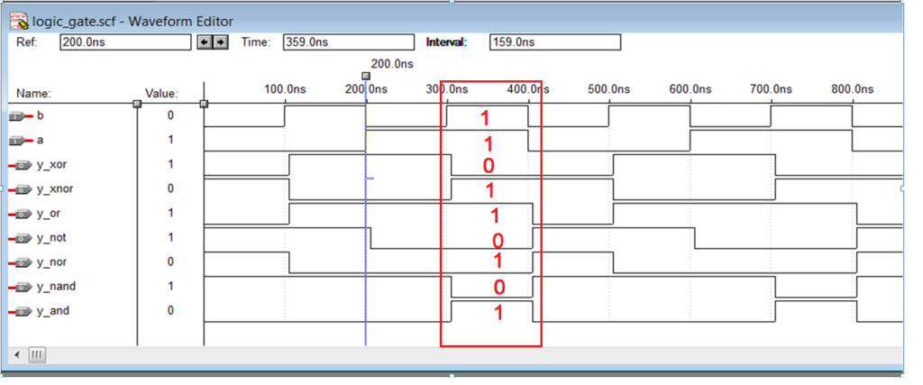
Now verify these output waveforms with the truth table of GATEs. For example, here, one case is highlighted with inputs A=1 and B=1. You can verify the other three cases also.

This is how you can build a simple logic GATE circuit in VHDL and verify its output with their truth table.

In the next tutorial, we shall see how to build NAND, NOR, XOR, and XNOR gates using three basic gates AND, OR, and NOT using VHDL.

Related Articles Read More >

VHDL
VHDL Tutorial 1: Introduction to VHDL
VHDL
VHDL Tutorial 2: VHDL programs
VHDL Tutorial – 22: Designing a 1-bit & an 8-bit comparator by using VHDL
VHDL Tutorial – 21: Designing an 8-bit, full-adder circuit using VHDL

Featured Tutorials

  • Remote Controlling Multiple Loads Using RF Module (Part 2/23)
  • Increasing Range of RF Module by Increasing Transmission Power (Part 3/23)
  • Increasing range of RF module by using antenna (Part 4/23)
  • Increasing the Range of RF Module by Using Antenna and Increasing Transmission Power (Part 5/23)
  • Controlling Multiple RF Receivers by Universal RF Transmitter (Part 6/23)
  • Multiple RF Receivers Controlled by a Universal RF transmitter based on Address Pin Configuration (Part 7/23)

Stay Up To Date

Newsletter Signup

EE Training Center Classrooms

“ee

“ee

“ee

“ee

“ee

Recent Articles

  • IAR Systems announces IEC and ISO certifications of its RISC-V development tools
  • Mathematical equations executed by an MCU
  • Infineon’s new Wi-Fi 6 brings reliable connectivity to smart homes
  • Toshiba releases compact LDO regulators for stabilizing DC power lines
  • Clap sensor using STM32 MCU
...

RSS EDABOARD.com Discussions

  • How can I explan this simple PWM creator Circuit
  • Can I use a Virtual clock instead of using a create_clock?
  • MCLR as digital input is resetting the device
  • Symmetrical Fully Differential Amplifier Layout
  • What is the DC voltage rating of this Y2 capacitor?

RSS Electro-Tech-Online.com Discussions

  • NTC flakey
  • Diode that only allows continuity at 13.5v?
  • Can two N-Channel MOSFETs be connected in series to perform a "AND" function?
  • Cycle Indicator Lights
  • #MEASURING OUTPUT VOLTAGE# Ideal laboratory power supply - YOURS requirements
Engineers Garage
  • Analog IC TIps
  • Connector Tips
  • DesignFast
  • EDABoard Forums
  • EE World Online
  • Electro-Tech-Online Forums
  • Microcontroller Tips
  • Power Electronic Tips
  • Sensor Tips
  • Test and Measurement Tips
  • 5G Technology World
  • About Us
  • Contact Us
  • Advertise

Copyright © 2021 WTWH Media LLC. All Rights Reserved. The material on this site may not be reproduced, distributed, transmitted, cached or otherwise used, except with the prior written permission of WTWH Media
Privacy Policy | Advertising | About Us

Search Engineers Garage

  • Projects and Tutorials
    • Circuit Design
    • Electronic Projects
      • 8051
      • Arduino
      • ARM
      • AVR
      • PIC
      • Raspberry pi
      • STM32
    • Tutorials
    • Components
  • Articles
    • Tech Articles
    • Insight
    • Invention Stories
    • How to
    • What Is
  • News
    • EE Design News
    • DIY Reviews
    • Guest Post
    • Sponsored Content
  • Forums
    • EDABoard.com
    • Electro-Tech-Online
    • EG Forum Archive
  • Digi-Key Store
    • Cables, Wires
    • Connectors, Interconnect
    • Discrete
    • Electromechanical
    • Embedded Computers
    • Enclosures, Hardware, Office
    • Integrated Circuits (ICs)
    • Isolators
    • LED/Optoelectronics
    • Passive
    • Power, Circuit Protection
    • Programmers
    • RF, Wireless
    • Semiconductors
    • Sensors, Transducers
    • Test Products
    • Tools
  • EE Resources
    • DesignFast
    • LEAP Awards
    • Oscilloscope Product Finder
    • Video
    • White Papers
    • Webinars
  • EE Learning Center
  • Women in Engineering