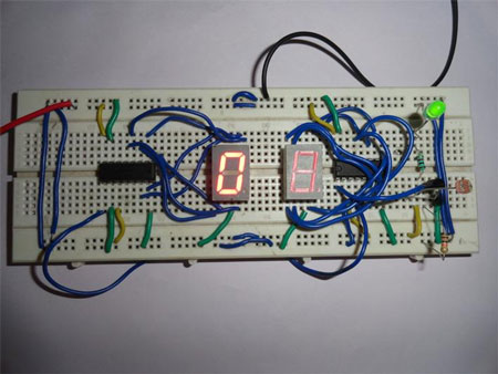
Visitor counter is based on popularly known 4026 decade counter and divider IC with 7 segment displays to display the number of visitors. In this circuit we are using LDR as a sensor for sensing the visitors with few more components. CD4033 is a Johnson counter IC commonly used in digital display. It contains 5 stage Johnson decade counter with decoder which converts the Johnson code to 7 segment decoded output. It means it will convert the input into numeric display which can be seen on 7 segment display or with the help of LED’s. It can be used for displaying analogue value, such as temperature with pic- microcontroller, and can be used for counting objects. In this, counter will advance on receiving a high at its clock pin (pin 1).
LDR is a device whose sensitivity depends upon the intensity of light falling on it. The resistance of LDR decreases when intensity of light falling on it increases and vice versa (resistance increases when intensity of light falling on it decreases). In dark or absence of light, LDR exhibits a resistance in the range of mega ohms which decreases too few hundred ohms in presence of bright light. This phenomenon can be measured with the help of multi-meter. For this you can keep your multi-meter in ohm or resistor measurement region. We are utilizing this property of LDR to act as a sensor, since a varying voltage drop can be obtained with varying light. In this circuit amount of light is vary because of the shadow of the visitor which falls on LDR. So care should be taken while mounting the LDR.
Working of visitor counter circuit-
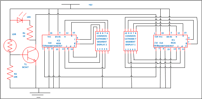
Assemble the circuit properly. Connect the pin 3 of both the IC 1 and 2 to supply to switch on the display. If pin 3 is connected to ground, we will not get display on 7 segment output and also connect the pin 15 which is a reset pin to ground so that when counting reaches to 99 it will reset the counter to zero. Also connect the pin 2 to ground if this pin is held high then counter will not advance.
Now apply power supply. Zero will be displayed on both the 7 segment display. As soon as visitor comes near to the LDR its shadow will fall on LDR and its resistance increases. This will provide a clock pulse to pin 1 (which is a clock input pin) of IC1 with the help of a transistor. Transistor is used to amplify the weak signals. After receiving the clock pulse, 4026 IC counter advances and 1 will be displayed on common cathode and 7 segment displays 1. When second person enters, same phenomenon occurs till count reaches 9. When it reaches 9 one cycle is completed. As you can see from circuit diagram pin 5 of IC1 is connected to pin 1 of IC2 to cascade another IC, after every 10th pulse it will go high to provide a clock pulse to IC2 to advance its counter that’s why we will receive a 1 on 7 segment common cathode display 2. Unit place number are displayed on display 1 and tens place numbers are displayed on display 2. After completion of each cycle, tens place advances to one. Similarly you can add N numbers of 4026 IC with 7 segment display.

Circuit Diagrams
Project Video
Filed Under: Electronic Projects
Filed Under: Electronic Projects


Questions related to this article?
👉Ask and discuss on EDAboard.com and Electro-Tech-Online.com forums.
Tell Us What You Think!!
You must be logged in to post a comment.