Engineers Garage

  • Electronic Projects & Tutorials
    • Electronic Projects
      • Arduino Projects
      • AVR
      • Raspberry pi
      • ESP8266
      • BeagleBone
      • 8051 Microcontroller
      • ARM
      • PIC Microcontroller
      • STM32
    • Tutorials
      • Audio Electronics
      • Battery Management
      • Brainwave
      • Electric Vehicles
      • EMI/EMC/RFI
      • Hardware Filters
      • IoT tutorials
      • Power Tutorials
      • Python
      • Sensors
      • USB
      • VHDL
    • Circuit Design
    • Project Videos
    • Components
  • Articles
    • Tech Articles
    • Insight
    • Invention Stories
    • How to
    • What Is
  • News
    • Electronic Product News
    • Business News
    • Company/Start-up News
    • DIY Reviews
    • Guest Post
  • Forums
    • EDABoard.com
    • Electro-Tech-Online
    • EG Forum Archive
  • DigiKey Store
    • Cables, Wires
    • Connectors, Interconnect
    • Discrete
    • Electromechanical
    • Embedded Computers
    • Enclosures, Hardware, Office
    • Integrated Circuits (ICs)
    • Isolators
    • LED/Optoelectronics
    • Passive
    • Power, Circuit Protection
    • Programmers
    • RF, Wireless
    • Semiconductors
    • Sensors, Transducers
    • Test Products
    • Tools
  • Learn
    • eBooks/Tech Tips
    • Design Guides
    • Learning Center
    • Tech Toolboxes
    • Webinars & Digital Events
  • Resources
    • Digital Issues
    • EE Training Days
    • LEAP Awards
    • Podcasts
    • Webinars / Digital Events
    • White Papers
    • Engineering Diversity & Inclusion
    • DesignFast
  • Guest Post Guidelines
  • Advertise
  • Subscribe

Visitor Counter

By Ashutosh Bhatt December 26, 2018

Visitor counter is based on popularly known 4026 decade counter and divider IC with 7 segment displays to display the number of visitors. In this circuit we are using LDR as a sensor for sensing the visitors with few more components. CD4033 is a Johnson counter IC commonly used in digital display. It contains 5 stage Johnson decade counter with decoder which converts the Johnson code to 7 segment decoded output. It means it will convert the input into numeric display which can be seen on 7 segment display or with the help of LED's. It can be used for displaying analogue value, such as temperature with pic- microcontroller, and can be used for counting objects. In this, counter will advance on receiving a high at its clock pin (pin 1).


LDR is a device whose sensitivity depends upon the intensity of light falling on it. The resistance of LDR decreases when intensity of light falling on it increases and vice versa (resistance increases when intensity of light falling on it decreases). In dark or absence of light, LDR exhibits a resistance in the range of mega ohms which decreases too few hundred ohms in presence of bright light. This phenomenon can be measured with the help of multi-meter. For this you can keep your multi-meter in ohm or resistor measurement region. We are utilizing this property of LDR to act as a sensor, since a varying voltage drop can be obtained with varying light. In this circuit amount of light is vary because of the shadow of the visitor which falls on LDR. So care should be taken while mounting the LDR.
Working of visitor counter circuit-
Assemble the circuit properly. Connect the pin 3 of both the IC 1 and 2 to supply to switch on the display. If pin 3 is connected to ground, we will not get display on 7 segment output and also connect the pin 15 which is a reset pin to ground so that when counting reaches to 99 it will reset the counter to zero. Also connect the pin 2 to ground if this pin is held high then counter will not advance.
Now apply power supply. Zero will be displayed on both the 7 segment display. As soon as visitor comes near to the LDR its shadow will fall on LDR and its resistance increases. This will provide a clock pulse to pin 1 (which is a clock input pin) of IC1 with the help of a transistor. Transistor is used to amplify the weak signals. After receiving the clock pulse, 4026 IC counter advances and 1 will be displayed on common cathode and 7 segment displays 1. When second person enters, same phenomenon occurs till count reaches 9. When it reaches 9 one cycle is completed. As you can see from circuit diagram pin 5 of IC1 is connected to pin 1 of IC2 to cascade another IC, after every 10th pulse it will go high to provide a clock pulse to IC2 to advance its counter that’s why we will receive a 1 on 7 segment common cathode display 2. Unit place number are displayed on display 1 and tens place numbers are displayed on display 2.  After completion of each cycle, tens place advances to  one. Similarly you can add N numbers of 4026 IC with 7 segment display.  

Visitor Counter

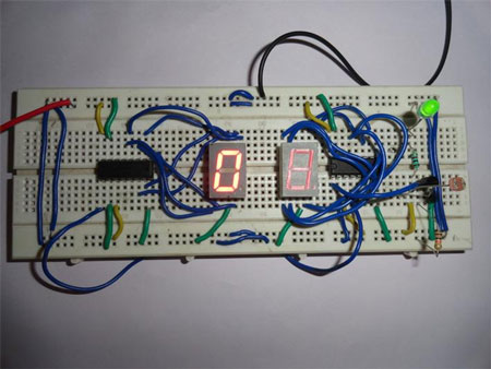
Fig. 1: Prototype of Circuit on Breadborad Showing working of Visitor Counter


Circuit Diagrams

Visitor-Counter_0

Project Video


Filed Under: Electronic Projects


Next Article

← Previous Article
Next Article →

Questions related to this article?
👉Ask and discuss on EDAboard.com and Electro-Tech-Online.com forums.


Tell Us What You Think!! Cancel reply

You must be logged in to post a comment.

EE TECH TOOLBOX

“ee
Tech Toolbox: Internet of Things
Explore practical strategies for minimizing attack surfaces, managing memory efficiently, and securing firmware. Download now to ensure your IoT implementations remain secure, efficient, and future-ready.

EE Learning Center

EE Learning Center
“engineers
EXPAND YOUR KNOWLEDGE AND STAY CONNECTED
Get the latest info on technologies, tools and strategies for EE professionals.

HAVE A QUESTION?

Have a technical question about an article or other engineering questions? Check out our engineering forums EDABoard.com and Electro-Tech-Online.com where you can get those questions asked and answered by your peers!


RSS EDABOARD.com Discussions

  • Reducing "shoot-through" in offline Full Bridge SMPS?
  • Checking line impedance
  • Why do I hear whistling sounds in my vents?
  • What is the purpose of using a VCVS?
  • Mains inverter with switching node going out on the mains cable!?

RSS Electro-Tech-Online.com Discussions

  • Why can't I breadboard this oscillator?
  • Failure of polypropylene motor-run capacitors
  • a point I can't understand about the sinc expression
  • Quick advice on remote car starter?
  • Wideband matching an electrically short bowtie antenna; 50 ohm, 434 MHz

Featured – RPi Python Programming (27 Part)

  • RPi Python Programming 21: The SIM900A AT commands
  • RPi Python Programming 22: Calls & SMS using a SIM900A GSM-GPRS modem
  • RPi Python Programming 23: Interfacing a NEO-6MV2 GPS module with Raspberry Pi
  • RPi Python Programming 24: I2C explained
  • RPi Python Programming 25 – Synchronous serial communication in Raspberry Pi using I2C protocol
  • RPi Python Programming 26 – Interfacing ADXL345 accelerometer sensor with Raspberry Pi

Recent Articles

  • AC-DC power supply extends voltage range to 800 V DC
  • Infineon’s inductive sensor integrates coil system driver, signal conditioning circuits and DSP
  • Arm Cortex-M23 MCU delivers 87.5 µA/MHz active mode
  • STMicroelectronics releases automotive amplifiers with in-play open-load detection
  • Convection-cooled power controller integrates EtherCat connectivity

EE ENGINEERING TRAINING DAYS

engineering

Submit a Guest Post

submit a guest post
Engineers Garage
  • Analog IC TIps
  • Connector Tips
  • Battery Power Tips
  • DesignFast
  • EDABoard Forums
  • EE World Online
  • Electro-Tech-Online Forums
  • EV Engineering
  • Microcontroller Tips
  • Power Electronic Tips
  • Sensor Tips
  • Test and Measurement Tips
  • 5G Technology World
  • Subscribe to our newsletter
  • About Us
  • Contact Us
  • Advertise

Copyright © 2025 WTWH Media LLC. All Rights Reserved. The material on this site may not be reproduced, distributed, transmitted, cached or otherwise used, except with the prior written permission of WTWH Media
Privacy Policy

Search Engineers Garage

  • Electronic Projects & Tutorials
    • Electronic Projects
      • Arduino Projects
      • AVR
      • Raspberry pi
      • ESP8266
      • BeagleBone
      • 8051 Microcontroller
      • ARM
      • PIC Microcontroller
      • STM32
    • Tutorials
      • Audio Electronics
      • Battery Management
      • Brainwave
      • Electric Vehicles
      • EMI/EMC/RFI
      • Hardware Filters
      • IoT tutorials
      • Power Tutorials
      • Python
      • Sensors
      • USB
      • VHDL
    • Circuit Design
    • Project Videos
    • Components
  • Articles
    • Tech Articles
    • Insight
    • Invention Stories
    • How to
    • What Is
  • News
    • Electronic Product News
    • Business News
    • Company/Start-up News
    • DIY Reviews
    • Guest Post
  • Forums
    • EDABoard.com
    • Electro-Tech-Online
    • EG Forum Archive
  • DigiKey Store
    • Cables, Wires
    • Connectors, Interconnect
    • Discrete
    • Electromechanical
    • Embedded Computers
    • Enclosures, Hardware, Office
    • Integrated Circuits (ICs)
    • Isolators
    • LED/Optoelectronics
    • Passive
    • Power, Circuit Protection
    • Programmers
    • RF, Wireless
    • Semiconductors
    • Sensors, Transducers
    • Test Products
    • Tools
  • Learn
    • eBooks/Tech Tips
    • Design Guides
    • Learning Center
    • Tech Toolboxes
    • Webinars & Digital Events
  • Resources
    • Digital Issues
    • EE Training Days
    • LEAP Awards
    • Podcasts
    • Webinars / Digital Events
    • White Papers
    • Engineering Diversity & Inclusion
    • DesignFast
  • Guest Post Guidelines
  • Advertise
  • Subscribe