Engineers Garage

  • Projects and Tutorials
    • Electronic Projects
      • 8051
      • Arduino
      • ARM
      • AVR
      • PIC
      • Raspberry pi
      • STM32
    • Tutorials
    • Circuit Design
    • Project Videos
    • Components
  • Articles
    • Tech Articles
    • Insight
    • Invention Stories
    • How to
    • What Is
  • News
    • Electronic Products News
    • DIY Reviews
    • Guest Post
  • Forums
    • EDABoard.com
    • Electro-Tech-Online
    • EG Forum Archive
  • Digi-Key Store
    • Cables, Wires
    • Connectors, Interconnect
    • Discrete
    • Electromechanical
    • Embedded Computers
    • Enclosures, Hardware, Office
    • Integrated Circuits (ICs)
    • Isolators
    • LED/Optoelectronics
    • Passive
    • Power, Circuit Protection
    • Programmers
    • RF, Wireless
    • Semiconductors
    • Sensors, Transducers
    • Test Products
    • Tools
  • EE Resources
    • DesignFast
    • LEAP Awards
    • Oscilloscope Product Finder
    • White Papers
    • Webinars
  • EE Learning Center
    • Design Guides
      • WiFi & the IOT Design Guide
      • Microcontrollers Design Guide
      • State of the Art Inductors Design Guide
  • Women in Engineering

Water Level Indicator with Display

By Ashutosh Bhatt

The use of water level indicator is common nowadays. This circuit of this project is simple, economical and versatile. It is used to switch on the motor pump when the level of water falls below the lowest level in tank.

This water level indicator with display is based on two IC that is 74147 IC and 4511 IC. Water level indicator has following advantage-


●     Most of the circuit display level of water with the help of LED. In this you will get display on common cathode 7 segment display.

●    Therefore it become easy to find the level of water in tank.

●    It can be easily installed in over headed tanks because of less components used in circuits.

●    It prevents the wastage of water due to over flow of tank.

●     Can be operated with the help of 12V battery or adaptors (converts 230V AC to 12V DC) readily available in markets.

[[wysiwyg_imageupload:9923:]]

Fig. 1: Prototype Of Water Level Indicator Circuit On Breadboard


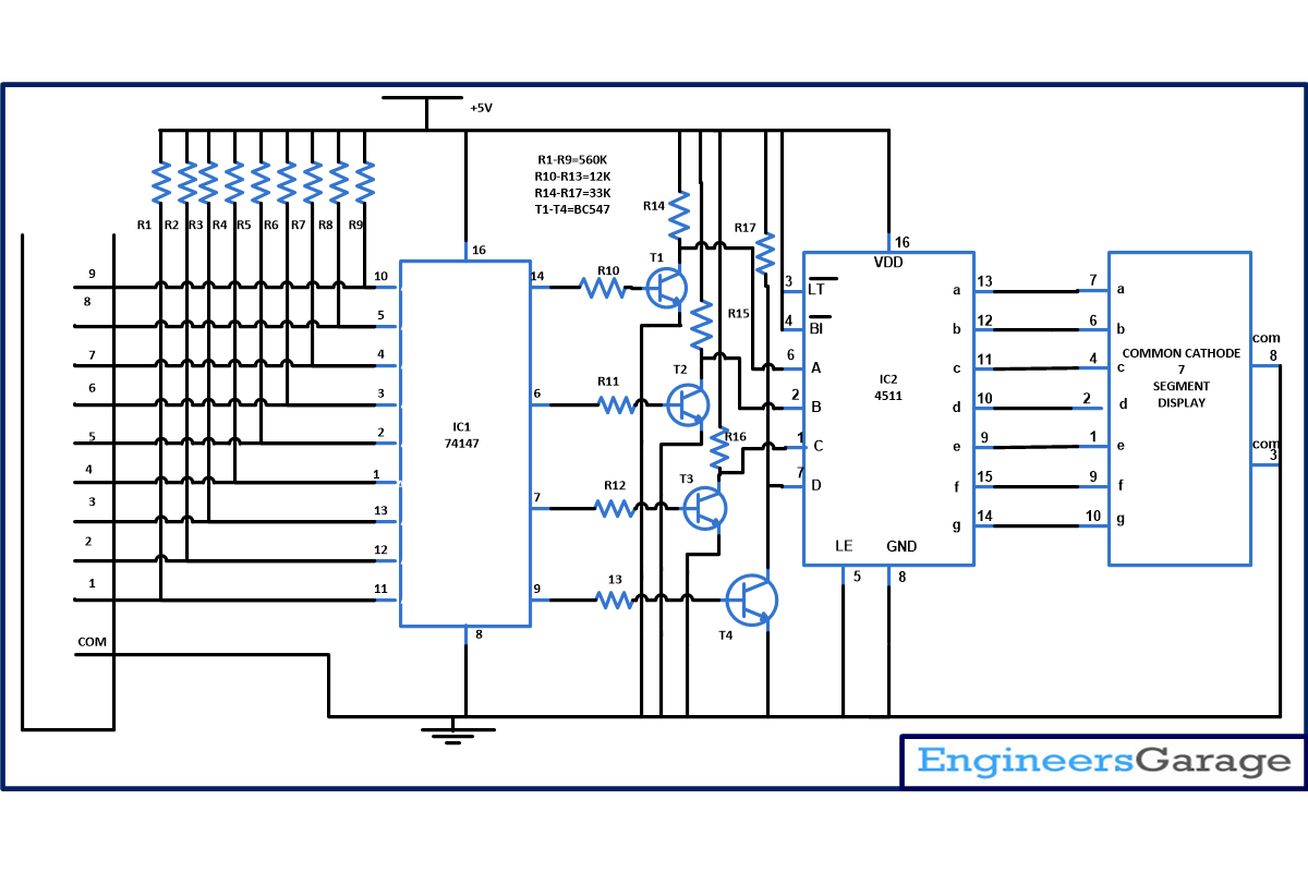
IC 74147 is a 9 input priority encoder IC which accept data from nine active low input and convert it into 4 binary active low output. When 2 or 3 output goes high simultaneously than output with highest priority is display on output that’s why it is called as priority encoder. This IC is also known as 10 line to 4 line priority encoder. Pin configuration and description of IC is shown below. 

 Pin Diagram and Pin Configuration Of 74147 IC

Fig. 2: Pin Diagram and Pin Configuration Of 74147 IC 

Truth table of IC- 

Truth table Of 74147 IC

Fig. 3: Truth Table Of 74147 IC 

CD4511 is a CMOS BCD to seven segment latch/decoder. This IC provides the facility of 4-bit storage latch, an 8421 BCD-to-seven segment decoder. It also provide you the of facility lamp test (). It is used to check that all segments of 7 segment is working properly or not. For testing momentarily make the pin low, in short used to test the display. Blanking input () is use to turn off or vary the brightness of the display. Latch enable (LE) is used to store BCD codes.  CD4511 is used in various application like in clock, watches, computer, calculators etc. Pin configuration of shown in figure below.

 Pin Diagram Of CD4511 IC

Fig. 4: Pin Diagram Of CD4511 IC

Here A, B, C, D are used to provide the BCD input where A is the least significant bit and D is the most significant bit. And a, b, c, d, e, f, g is same as the a, b, c, d, e, f, g  of seven segment display. 

Working of IC is very simple. Initially consider that tank is empty, when power supply is on  all the input  of IC1 is  high. From truth table of IC1 you can see that is if input is high then it will give you high on output pin also. This will make the input pin of IC2 low and 0 is displayed on seven segment display.

 Now when water in tank reaches level 1 than it will make the pin 11 of IC1 low and remaining pin remain pin high as a result we will get a output from pin 9 of IC1. From the truth table you can see bar on input and output means output is complemented so to make the low signal high we are providing the output from IC1 to input of IC2 with the help of a transistor. Now IC2 convert the decimal code to BCD code received from IC1. And numeric 1 is displayed on 7 segment display. 

Similarly when level in the tank reaches to level 2 it will make pin 12 of IC1 low and 11 is already low but 74147 is a priority encoder that’s why we will receive output from pin 7 and again this low signals are converted into high output with the help of transistor T3 and we will get numeric 2 display  on 7 segment display. This indicate that water has reached to level 2. 

As water in tank fills we will get numeric 3, 4 ….9  to be display. As soon as numeric 9 is display we came to know that tank is fill and we can switch off the motor to avoid wastage of water. 

You can also use 74148 IC in place of 74147. 74148 is also a 8 to 3 line priority encoder.

Circuit Diagrams

Circuit-Diagram-Water-Level-Indicator-Display

Project Components

  • Resistor
  • Seven Segment Display
  • Transistor BC547

Project Video


Filed Under: Electronic Projects
Tagged With: water level indicator
 

Questions related to this article?
👉Ask and discuss on Electro-Tech-Online.com and EDAboard.com forums.


Tell Us What You Think!! Cancel reply

You must be logged in to post a comment.

HAVE A QUESTION?

Have a technical question about an article or other engineering questions? Check out our engineering forums EDABoard.com and Electro-Tech-Online.com where you can get those questions asked and answered by your peers!


Featured Tutorials

  • PS2 Keyboard To Store Text In SD Card Using Arduino Circuit Setup On Breadboard
    How To Use PS2 Keyboard To Store Text In SD Card Using Arduino- (Part 42/49)
  • Wireless Path Tracking System Using Mouse, XBee And Arduino Circuit Setup On Breadboard
    How To Make A Wireless Path Tracking System Using Mouse, XBee And Arduino- (Part 43/49)
  • How to Make a Wireless Keyboard Using Xbee with Arduino- (Part 44/49)
  • Making Phone Call From GSM Module Using Arduino Circuit Setup On Breadboard
    How to Make Phonecall From GSM Module Using Arduino- (Part 45/49)
  • How to Make a Call using Keyboard, GSM Module and Arduino
    How To Make A Call Using Keyboard, GSM Module And Arduino- (Part 46/49)
  • Receiving SMS Using GSM Module With Arduino Prototype
    How to Receive SMS Using GSM Module with Arduino- (Part 47/49)

Stay Up To Date

Newsletter Signup

Sign up and receive our weekly newsletter for latest Tech articles, Electronics Projects, Tutorial series and other insightful tech content.

EE Training Center Classrooms

EE Classrooms

Recent Articles

  • What is a low power design?
  • Renesas partners with Tata to accelerate progress in advanced electronics
  • STMicroelectronics’ new touchscreen controller for smartphones enables longer runtime
  • Samsung unveils ISOCELL image sensor with industry’s smallest 0.56μm pixel
  • Renesas and Cyberon to deliver integrated voice-user interface solutions

Most Popular

5G 555 timer circuit 8051 ai Arduino atmega16 automotive avr bluetooth dc motor display Electronic Part Electronic Parts Fujitsu ic infineontechnologies integratedcircuit Intel IoT ir lcd led maximintegratedproducts microchip microchiptechnology Microchip Technology microcontroller microcontrollers mosfet motor powermanagement Raspberry Pi remote renesaselectronics renesaselectronicscorporation Research samsung semiconductor sensor software STMicroelectronics switch Technology vishayintertechnology wireless

RSS EDABOARD.com Discussions

  • Code Optimization
  • Natural Convection Heatsink for 80W power dissipation?
  • Code Optimization
  • Natural Convection Heatsink for 80W power dissipation?
  • Help identifying drop in ssignal

RSS Electro-Tech-Online.com Discussions

  • intro to PI
  • Lighting a .010 green fiber optic with led
  • Bridge purpose in connecting the two functional circuit
  • ICM7555 IC duty cycle limit at high frequency?
  • How to quickly estimate lead acid battery capacity ?
Engineers Garage
  • Analog IC TIps
  • Connector Tips
  • DesignFast
  • EDABoard Forums
  • EE World Online
  • Electro-Tech-Online Forums
  • Microcontroller Tips
  • Power Electronic Tips
  • Sensor Tips
  • Test and Measurement Tips
  • 5G Technology World
  • About Us
  • Contact Us
  • Advertise

Copyright © 2022 WTWH Media LLC. All Rights Reserved. The material on this site may not be reproduced, distributed, transmitted, cached or otherwise used, except with the prior written permission of WTWH Media
Privacy Policy | Advertising | About Us

Search Engineers Garage

  • Projects and Tutorials
    • Electronic Projects
      • 8051
      • Arduino
      • ARM
      • AVR
      • PIC
      • Raspberry pi
      • STM32
    • Tutorials
    • Circuit Design
    • Project Videos
    • Components
  • Articles
    • Tech Articles
    • Insight
    • Invention Stories
    • How to
    • What Is
  • News
    • Electronic Products News
    • DIY Reviews
    • Guest Post
  • Forums
    • EDABoard.com
    • Electro-Tech-Online
    • EG Forum Archive
  • Digi-Key Store
    • Cables, Wires
    • Connectors, Interconnect
    • Discrete
    • Electromechanical
    • Embedded Computers
    • Enclosures, Hardware, Office
    • Integrated Circuits (ICs)
    • Isolators
    • LED/Optoelectronics
    • Passive
    • Power, Circuit Protection
    • Programmers
    • RF, Wireless
    • Semiconductors
    • Sensors, Transducers
    • Test Products
    • Tools
  • EE Resources
    • DesignFast
    • LEAP Awards
    • Oscilloscope Product Finder
    • White Papers
    • Webinars
  • EE Learning Center
    • Design Guides
      • WiFi & the IOT Design Guide
      • Microcontrollers Design Guide
      • State of the Art Inductors Design Guide
  • Women in Engineering