● The water level indicator is used to measure the level of water present in the tank. This circuit not only indicates the amount of water present in overhead tank but it also gives an alarm when the tank is full.
● Water level indicator gives you an indication on 7 segment display by displaying E, P and C for empty, partially fill and completely fill, respectively.
● Water level indicator also gives you a display in the form of LED connected to it, you can also connect different color LED to distinguish the level of water present in it.
The circuit is built around two IC’s namely 7408, 7404, 7 segment common cathode display and few more components. IC7408 is Quad two input AND gate and IC7404 is a hex inverting gate.
[[wysiwyg_imageupload:7850:]]
Fig. 1: Prototype Of Water Level Indicator CirCuit On Breadboard
To understand the working of circuit one must know the truth table of 7408 and 7404 IC. 7408 IC gives you output as high or logic one when both the inputs are high otherwise we will receive low output. Quad input AND gate has four independent AND gates on a single IC.
Similarly 7404 is an inverter IC which will give you high output when low input is applied and vice versa. Inverter IC has 6 independent NOT gates present on a single IC.
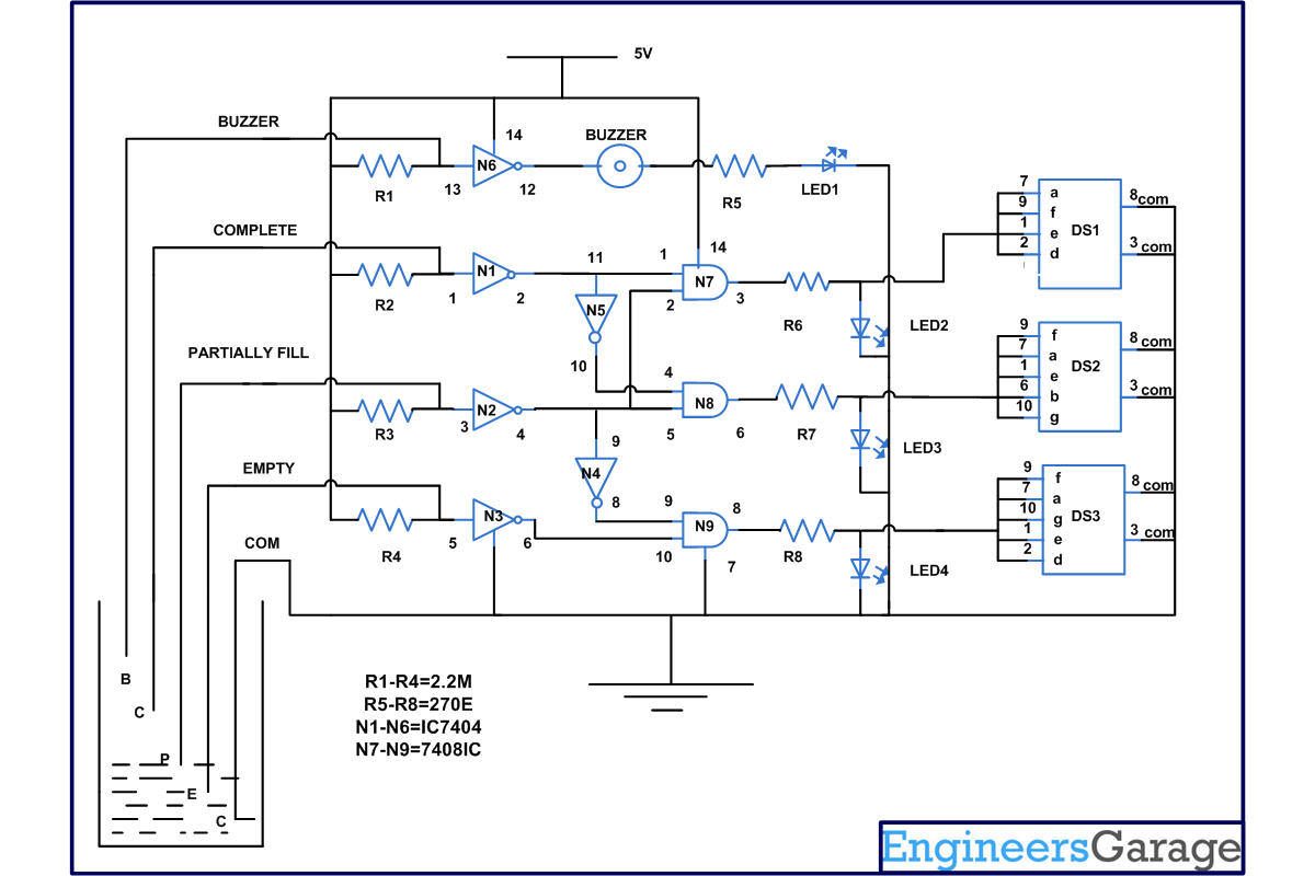
In this circuit, we are using 5 sensors to sense the level of water (one for Ground or Com, one for E, one for P, one for C and one for the buzzer). From the circuit diagram you can see that initially all input pins of 7404 IC are connected to supply with the help of 2.2Mohm resistor. Now consider the case when tank is empty: input pin 5 of IC 7404 is low as it is touching with the com sensor. This will make the output pin 6 high which is supplied to input pin 10 of gate N9 high. Pin 9 of gate N9 is also high because input pin 3 of gate N2 is high (connected to supply with the help of resistor). This makes pin 4 of gate N2 low and pin 8 of gate N4 becomes high. Hence, we will receive a high at output pin 8 which will in switch on the LED and display. On 7 segment display, we will get the alphabet E to empty.
When water reaches at the mid or partially filled level, pin 3 of gate N2 becomes low, which makes input pin 5 of gate N8 high. Pin 4 of gate N2 is also high because input pin 1 of gate N1 is high which will in turn make the output low. This low input is supplied to pin 11 of gate N5 and output pin 10 of gate N5 become high. Therefore both the pins of gate N8 are high which will glow the LED and common cathode 7 segment display. On display, we will get the alphabet P to partially fill.
Similar phenomenon happens when water reaches the completely filled level. Pin 1 of N1 becomes low which will make input pin 1 of N7 high and pin 2 of N1 also becomes high. Therefore, we will receive high at output pin 3 of gate N7 and the common cathode LED display and LED connected to it start glowing. On display we will get the alphabet C to completely fill.
When the water is completely filled, pin 13 of gate N6 goes low to make the output pin 12 high and the buzzer connected to it start sounding. All sensors must be constructed from non corrosive material.
Also check the water level indicator project using 8051 microcontroller
Circuit Diagrams
Project Components
Project Video
Filed Under: Electronic Projects
Filed Under: Electronic Projects


Questions related to this article?
👉Ask and discuss on EDAboard.com and Electro-Tech-Online.com forums.
Tell Us What You Think!!
You must be logged in to post a comment.