Engineers Garage

  • Electronic Projects & Tutorials
    • Electronic Projects
      • Arduino Projects
      • AVR
      • Raspberry pi
      • ESP8266
      • BeagleBone
      • 8051 Microcontroller
      • ARM
      • PIC Microcontroller
      • STM32
    • Tutorials
      • Audio Electronics
      • Battery Management
      • Brainwave
      • Electric Vehicles
      • EMI/EMC/RFI
      • Hardware Filters
      • IoT tutorials
      • Power Tutorials
      • Python
      • Sensors
      • USB
      • VHDL
    • Circuit Design
    • Project Videos
    • Components
  • Articles
    • Tech Articles
    • Insight
    • Invention Stories
    • How to
    • What Is
  • News
    • Electronic Product News
    • Business News
    • Company/Start-up News
    • DIY Reviews
    • Guest Post
  • Forums
    • EDABoard.com
    • Electro-Tech-Online
    • EG Forum Archive
  • DigiKey Store
    • Cables, Wires
    • Connectors, Interconnect
    • Discrete
    • Electromechanical
    • Embedded Computers
    • Enclosures, Hardware, Office
    • Integrated Circuits (ICs)
    • Isolators
    • LED/Optoelectronics
    • Passive
    • Power, Circuit Protection
    • Programmers
    • RF, Wireless
    • Semiconductors
    • Sensors, Transducers
    • Test Products
    • Tools
  • Learn
    • eBooks/Tech Tips
    • Design Guides
    • Learning Center
    • Tech Toolboxes
    • Webinars & Digital Events
  • Resources
    • Digital Issues
    • EE Training Days
    • LEAP Awards
    • Podcasts
    • Webinars / Digital Events
    • White Papers
    • Engineering Diversity & Inclusion
    • DesignFast
  • Guest Post Guidelines
  • Advertise
  • Subscribe

Wave Counter using ARM7 Microcontroller

By Sunny Kushwaha April 21, 2008

Project has basically two modules:-

1)                  Wave generator
2)                  Wave counter
Overview of LPC2138 ARM Microcontroller based Wave Counter
Fig. 1: Overview of LPC2138 ARM Microcontroller based Wave Counter
 Wave generator generates square waves of certain frequency. Wave counter counts the positive edges and thus the waves and displays the frequency on a serial device like a laptop or serial LCD etc.
Diagram showing working principle of Wave Counter
Fig. 2: Diagram showing working principle of Wave Counter
MATERIALS REQUIRED
1)                  WAVE GENERATOR (OPTIONAL) 
–          1 lpc2148 board = Rs 2000
–          Or atmega16 board =Rs 250
2)                  WAVE COUNTER
–          1 lpc2148 board = Rs 2000
–          Some serial display
TOTAL=Rs 2000-2200
 WORKING
– WAVE GENERATOR (OPTIONAL)
Basically it generates square waves of certain frequency. The concept here used is time scheduling. Timer 0 is set as fast interrupt request and after every 1 ms the interrupt is generated and the ISR is executed. In the ISR a set variable is taken and is given certain value eg=50. So as After every 1 ms ISR is executed a count is incremented and compared with set and as a match is found the output pins initially low are set high that is toggled and count=0. So again as ISR is executed count is incremented and again when count = set output pin is set to 0 (toggled) from high so like this square waves are generated of time period=2*set and the
Frequency= (1000/ (2*set))
Eg set = 50
Time period = 100ms
Frequency = 1000/100 = 10 Hz
And same is found on serial display through wave counter and can be seen in simulation.
WAVE COUNTER
In this input wave is given through I/O pin and then counting begins. Here also time scheduling is used. Timer 0 is set as fast interrupt request and after every 2 us ISR is executed. And a static variable count is incremented and if count==1 the status at I/O pin is stored in pre variable. Then again after 2 us ISR is executed and count is again incremented if count==2 status at input I/O pin is stored in nex variable and count=0. So after this we have previous state in pre and next state in nex. Then pre is compared with 0 and nex with 1 now if pre == 0 and nex == 1 means a positive edge has occurred so another variable num is incremented num++. To keep track of time another variable task[0] is incremented after every 2 us and as it equals 16000 i.e time elapsed = 32000 us or 30-32 ms this is actually done by calibrating task[0]. Now as task[0]==16000 the value stored in num at that time equals frequency of the wave. The same is sent to serial terminal and displayed.
– I used 3 pins 3, 4, 5 of lpc2148 to generate waves and choose set=50 so frequency=10.
– For wave counter i.e second lpc2148 I used 2, 3, 4 pins as input pins.
– I displayed result as follows:-
10 11 10 n
11 11 10 n
Here 3 values represents frequency at 3 pins and if frequency < 40 then letter displayed = n
Otherwise letter displayed = s
IMPORTANT INFORMATION
– IDE used KEILUVISION 4
– SIMULATED on PROTEUS 7.1
– BOARD used LPC2148
– Codes provided
            – pulse_gen
            – wave_counter
– Hex files provided
            – pulse_gen.hex
            – wave_counter.hex
– Some additional .h and .c are also provided like delay, uart0, timerfiq etc.
All these are in their respective folders i.e:-
-wave_counter
-wave_generator
-Build schematic on proteus load the provided hex files in respective lpc2148 then run to see output.


Circuit Diagrams

Circuit-Diagram-LPC2138-ARM-Microcontroller-Based-Wave-Counter
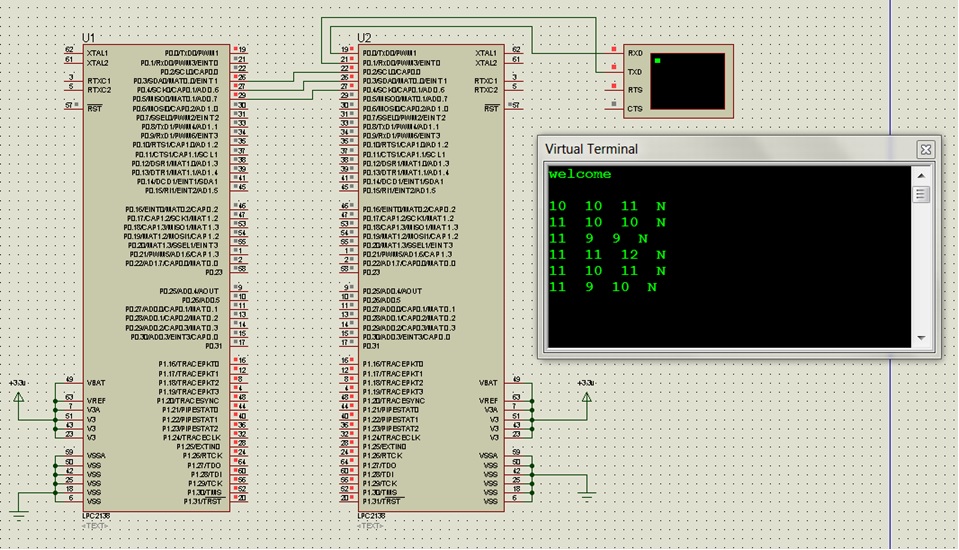
Circuit-Diagram-LPC2138-Microcontroller-Based-Wave-Counter
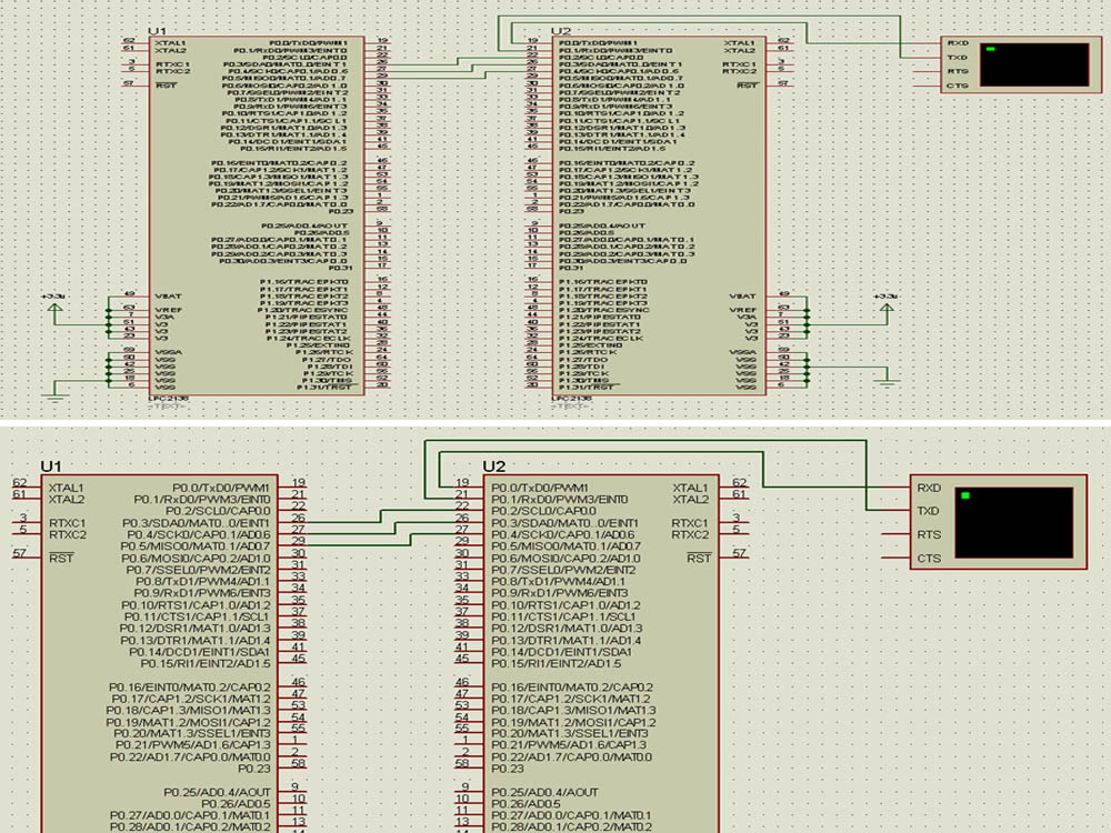
Project Video


Filed Under: Electronic Projects
Tagged With: arm7, wave counter, wave generator
 

Next Article

← Previous Article
Next Article →

Questions related to this article?
👉Ask and discuss on Electro-Tech-Online.com and EDAboard.com forums.


Tell Us What You Think!! Cancel reply

You must be logged in to post a comment.

EE TECH TOOLBOX

“ee
Tech Toolbox: 5G Technology
This Tech Toolbox covers the basics of 5G technology plus a story about how engineers designed and built a prototype DSL router mostly from old cellphone parts. Download this first 5G/wired/wireless communications Tech Toolbox to learn more!

EE Learning Center

EE Learning Center
“engineers
EXPAND YOUR KNOWLEDGE AND STAY CONNECTED
Get the latest info on technologies, tools and strategies for EE professionals.

HAVE A QUESTION?

Have a technical question about an article or other engineering questions? Check out our engineering forums EDABoard.com and Electro-Tech-Online.com where you can get those questions asked and answered by your peers!


RSS EDABOARD.com Discussions

  • Exporting sensor readings as data...
  • Inconsistent Charge Termination Voltage with battery charger
  • 21V keeps getting shorted to my UART line.
  • Voltage mode pushpull is a nonsense SMPS?
  • Voltage mode push pull with extra DC blocking capacitor

RSS Electro-Tech-Online.com Discussions

  • Is AI making embedded software developers more productive?
  • Why can't I breadboard this oscillator?
  • using a RTC in SF basic
  • Parts required for a personal project
  • Cataract Lens Options?

Featured – RPi Python Programming (27 Part)

  • RPi Python Programming 21: The SIM900A AT commands
  • RPi Python Programming 22: Calls & SMS using a SIM900A GSM-GPRS modem
  • RPi Python Programming 23: Interfacing a NEO-6MV2 GPS module with Raspberry Pi
  • RPi Python Programming 24: I2C explained
  • RPi Python Programming 25 – Synchronous serial communication in Raspberry Pi using I2C protocol
  • RPi Python Programming 26 – Interfacing ADXL345 accelerometer sensor with Raspberry Pi

Recent Articles

  • GigaDevice launches GD32C231 MCU series with 48MHz Cortex-M23 core and 64KB Flash
  • Advanced Energy releases 425 W CF-rated medical power supply in 3.5 x 6 x 1.5-inch format”
  • LEM combines shunt and Hall effect sensing in 2000 A current measurement unit
  • What is AWS IoT Core and when should you use it?
  • AC-DC power supply extends voltage range to 800 V DC

EE ENGINEERING TRAINING DAYS

engineering

Submit a Guest Post

submit a guest post
Engineers Garage
  • Analog IC TIps
  • Connector Tips
  • Battery Power Tips
  • DesignFast
  • EDABoard Forums
  • EE World Online
  • Electro-Tech-Online Forums
  • EV Engineering
  • Microcontroller Tips
  • Power Electronic Tips
  • Sensor Tips
  • Test and Measurement Tips
  • 5G Technology World
  • Subscribe to our newsletter
  • About Us
  • Contact Us
  • Advertise

Copyright © 2025 WTWH Media LLC. All Rights Reserved. The material on this site may not be reproduced, distributed, transmitted, cached or otherwise used, except with the prior written permission of WTWH Media
Privacy Policy

Search Engineers Garage

  • Electronic Projects & Tutorials
    • Electronic Projects
      • Arduino Projects
      • AVR
      • Raspberry pi
      • ESP8266
      • BeagleBone
      • 8051 Microcontroller
      • ARM
      • PIC Microcontroller
      • STM32
    • Tutorials
      • Audio Electronics
      • Battery Management
      • Brainwave
      • Electric Vehicles
      • EMI/EMC/RFI
      • Hardware Filters
      • IoT tutorials
      • Power Tutorials
      • Python
      • Sensors
      • USB
      • VHDL
    • Circuit Design
    • Project Videos
    • Components
  • Articles
    • Tech Articles
    • Insight
    • Invention Stories
    • How to
    • What Is
  • News
    • Electronic Product News
    • Business News
    • Company/Start-up News
    • DIY Reviews
    • Guest Post
  • Forums
    • EDABoard.com
    • Electro-Tech-Online
    • EG Forum Archive
  • DigiKey Store
    • Cables, Wires
    • Connectors, Interconnect
    • Discrete
    • Electromechanical
    • Embedded Computers
    • Enclosures, Hardware, Office
    • Integrated Circuits (ICs)
    • Isolators
    • LED/Optoelectronics
    • Passive
    • Power, Circuit Protection
    • Programmers
    • RF, Wireless
    • Semiconductors
    • Sensors, Transducers
    • Test Products
    • Tools
  • Learn
    • eBooks/Tech Tips
    • Design Guides
    • Learning Center
    • Tech Toolboxes
    • Webinars & Digital Events
  • Resources
    • Digital Issues
    • EE Training Days
    • LEAP Awards
    • Podcasts
    • Webinars / Digital Events
    • White Papers
    • Engineering Diversity & Inclusion
    • DesignFast
  • Guest Post Guidelines
  • Advertise
  • Subscribe