There are many different kind of waveforms like sine wave, cosine wave, square wave, triangular wave, sawtooth wave, pulses, spikes, stair-case wave, ramp etc. All these waveforms are generated using oscillator circuits. And basically there are three types of oscillators only
- Sine wave oscillator
- Square wave oscillator
- Pulse generator
Then how other types of waveforms can be generated?
The answer is waveform converter circuits. Such circuits convert one type of wave into other. The function generator itself uses such circuits to generate different kinds of waveforms.
These circuits are very much useful when some circuits require one specific kind of wave as an input. For example
· The input to VCO (voltage controlled oscillator) is sawtooth wave only
· The input to any digital (CMOS or TTL) circuit is pulses only
So here I have presented 3 of such circuits that convert one type of wave into another. These circuits can be easily build on general purpose PCB or even on bread board using very few components and can be tested using general laboratory instruments.
So let us first collect the required components and instruments to build and test these circuits
Required Instruments:
· Dual power supply
· Function generator
· DSO (or CRO)
Required Components:
· IC LM741 – operational amplifier
· Resistor – 4700 ?
· Capacitor – 0.01 µF
Along with these components and instruments, you require following apparatus also
Required Apparatus:
· Bread board – to mount component
· Connecting wires – to connect component
· CRO probes – to connect input and output of circuit with function generator and CRO
Now let us start with very simple circuit that converts sine wave into square wave
Sine wave to square wave converter circuit
Circuit description:

Fig. 1: Circuit Diagram of LM741 OPAMP IC based Sine Wave to Square Wave Converter
· Sine wave input is applied at inverting terminal (2)
· Non inverting terminal (3) is grounded
· Square wave output is taken from output terminal (6)
· +5 V supply is given to +Vcc terminal (7) and -5 V supply is given to –Vee terminal (4)
Now have a look at how the above circuit works.
Circuit operation:
When IC LM741 is connected in comparator mode it converts sine wave into square wave of same frequency. The sine wave input is applied at inverting terminal of chip and non inverting terminal is grounded. So IC741 compares input on inverting terminal with 0 V. During positive cycle the input at inverting terminal is more than non inverting terminal so the output of chip will be +Vcc. While during negative cycle the input at inverting terminal is less than non inverting terminal so the output of chip will be –Vcc. Thus the output swings from +Vcc to –Vcc and so on as sine wave input cycle changes.
· A sine wave of around 1 KHz with at least 2 Vpp (-1 V to +1 V) is applied at the input
· In positive cycle of input, as it crosses 0 V mark, the voltage at inverting terminal is more than non inverting terminal. So output switches to -5 V
· Similarly in negative cycle of input, as it crosses 0 V mark, the voltage at inverting terminal becomes less than non inverting terminal. So output switches to +5 V.
· Thus output swings from +5 V to – 5 V and -5 V to +5 V as input sine wave crosses 0 mark
· So the frequency of input sine wave and output square wave are same.
Now after understanding the circuit operation and building the circuit on bread board next is to test the circuit. So follow the step by step procedure to test the circuit
Test Procedure:
- Set 4 Vpp @ 1 KHz sine wave in function generator by connecting its output directly to 1st channel of DSO using CRO probes
- Apply this sine wave to the input of circuit
- Connect the output of the circuit to 2nd channel of DSO using CRO probe
- Connect +5 V, – 5V and ground to the circuit from dual power supply
- Switch on power supply
- Observe input and output waveforms on DSO
Here is the photograph of test setup of circuit.

Fig. 2: Image showing Input and Output Waveforms of LM741 IC based Sine Wave to Square Wave Converter on an Oscilloscope
When you follow above step by step procedure you will get output on CRO (DSO) as per given photograph.

Fig. 3: Image showing Input and Output Waveforms of LM741 IC based Sine Wave to Square Wave Converter on Display Panel of an Oscilloscope
In above photograph sine wave in yellow colour is an input to circuit applied to 1st channel of DSO and square wave in blue colour is an output from circuit applied to 2nd channel of DSO
You would be wondering where this circuit can be used?
The answer is, this circuit can be used where it is required that input should have only two states either positive or negative. Also by applying some reference voltage at non inverting terminal the circuit can generate PWM wave whose pulse width can be varied by varying reference voltage.
Now let’s move ahead with next circuit that converts square wave into triangle wave.
Square Wave to Triangle Wave Converter Circuit
Circuit description:

Fig. 4: Circuit Diagram of LM741 OPAMP IC based Square Wave to Triangular Wave Converter
· A 4700 Ohm resistor is connected between input and inverting terminal (2)
· A 0.01 µF capacitor is connected between inverting terminal (2) and output (6)
· Non inverting terminal (3) is grounded
· +5 V supply is given to +Vcc terminal (7) and -5 V supply is given to –Vee terminal (4)
Circuit operation:
When a square wave input is applied to an integrator circuit it generates triangle wave in the output. An integrator circuit can be built using operational amplifier, one resistor and a capacitor. When a constant voltage is given to capacitor through resistor, it charges to max voltage and produces linear ramp. So this principle is used to convert square wave into triangle wave. In square wave there are only two voltage levels +V and –V. So during positive cycle of square wave when voltage is +V, capacitor charges to +V and produces positive ramp. Similarly during negative cycle capacitor charges to –V and produces negative ramp. And thus it produces continuous positive and negative ramps – means triangle wave.
· A square wave of around 1 KHz with at least 2 Vpp (-1 V to +1 V) is applied at the input
· In positive cycle of wave, the voltage at inverting terminal is more than non inverting terminal. So output of circuit is –Vee. The capacitor charges with constant current source and produces negative ramp and reaches to –Vee.
· Similarly in negative cycle of input, the voltage at inverting terminal becomes less than non inverting terminal. So output will be +Vcc. The capacitor charges with constant current source and produces positive ramp and reaches to +Vcc.
· Thus as square wave switches from +V to –V, the circuit output switches from positive ramp to negative ramp and vice versa and produces
Once again follow the same test procedure that you did for previous circuit. The input to the circuit is 4 Vpp @ 1 KHz square wave. Here is the photograph of test setup of circuit.

Fig. 5: Image showing Input and Output Waveforms of LM741 IC based Square Wave to Triangle Wave Converter on an Oscilloscope
You will get the input-output waveforms as shown in given photograph
Fig. 6: Image showing Input and Output Waveforms of LM741 IC based Square Wave to Triangular Wave Converter on Display Panel of an Oscilloscope
In above photograph square wave in yellow colour is an input to circuit applied to channel 1 of DSO and triangle wave in blue colour is an output from circuit applied to 2nd channel of DSO
The last circuit performs reverse action of above circuit. It converts triangular wave into square wave.
Triangle Wave to Square Wave Converter Circuit
Circuit description:

Fig. 7: Circuit Diagram of LM741 OPAMP IC based Triangle Wave to Square Wave Converter
· A 0.01 µF capacitor is connected between inverting terminal (2) and input signal
· A 10 K? resistor is connected between output (6) and inverting terminal (2)
· Non inverting terminal (3) is grounded
· +5 V supply is given to +Vcc terminal (7) and -5 V supply is given to –Vee terminal (4)
Circuit operation:
When a triangle wave input is applied to a differentiator circuit it generates square wave in the output. A differentiator circuit can be built using operational amplifier, one resistor and a capacitor. A differentiator gives differential output of given input. So when triangle wave given as an input it is differentiated and square wave output is produces.
· A triangle wave of around 10 KHz with at least 2 Vpp (-1 V to +1 V) is applied at the input
· This input is differentiated because output equation is
Vout = R1×C1×dVin
Dt
· So during positive ramp the output remains fixed at –Vee and during negative ramp the output will be +Vcc
· Thus the output switches from +Vcc to –Vee and so on – means produces square wave
Make a test setup as per previous two circuits. The only difference is input to the circuit is 4 Vpp @ 10 KHz triangle wave. Here is the photograph of input-output waveforms on DSO.

Fig. 8: Image showing Input and Output Waveforms of LM741 IC based Triangular Wave to Square Wave Converter on Display Panel of an Oscilloscope
In above photograph triangle wave in yellow colour is an input to circuit applied to channel 1 of DSO and square wave in blue colour is an output from circuit applied to 2nd channel of DSO.
So here I have presented three simple circuits that convert one type of wave into another. Such circuits can also be built like
· A simple transistor switch circuit can convert any kind of input wave into pulse output.
· A simple RC phase shift circuit can convert sine wave into cosine wave and vice versa
Circuit Diagrams
| Circuit-Diagram-LM741-OPAMP-IC-Based-Square-Wave-Triangle-Wave-Converter | 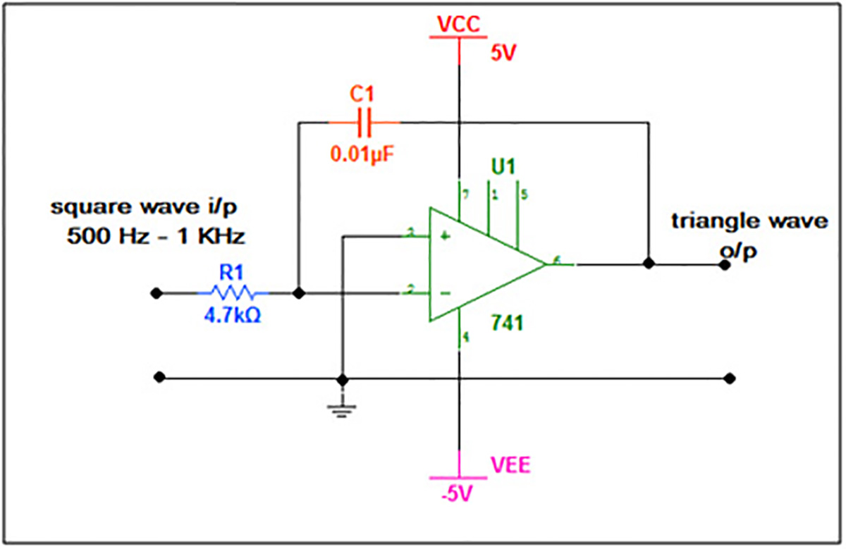 |
| Circuit-Diagram-LM741-OPAMP-IC-Based-Triangle-Wave-Square-Wave-Converter | 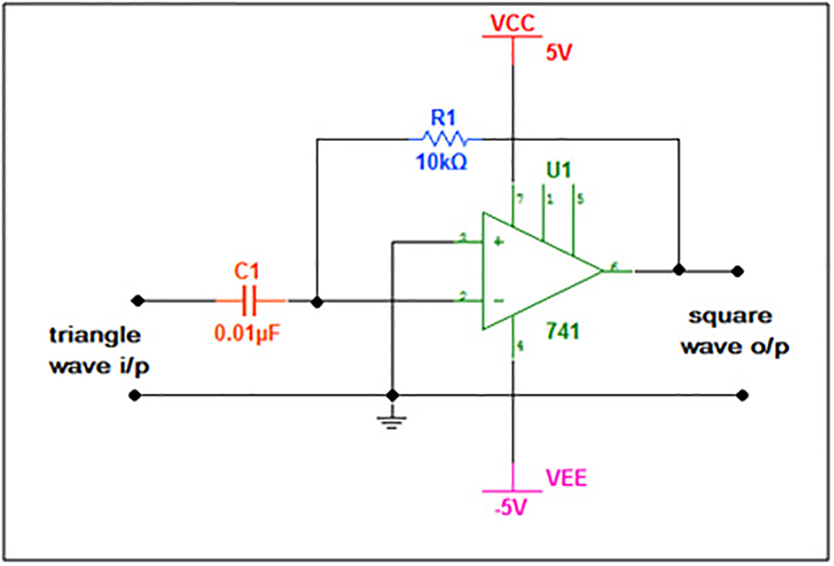 |
Filed Under: Electronic Projects

Questions related to this article?
👉Ask and discuss on EDAboard.com and Electro-Tech-Online.com forums.
Tell Us What You Think!!
You must be logged in to post a comment.