Engineers Garage

  • Projects and Tutorials
    • Electronic Projects
      • 8051
      • Arduino
      • ARM
      • AVR
      • PIC
      • Raspberry pi
      • STM32
    • Tutorials
    • Circuit Design
    • Project Videos
    • Components
  • Articles
    • Tech Articles
    • Insight
    • Invention Stories
    • How to
    • What Is
  • News
    • Electronic Products News
    • DIY Reviews
    • Guest Post
  • Forums
    • EDABoard.com
    • Electro-Tech-Online
    • EG Forum Archive
  • Digi-Key Store
    • Cables, Wires
    • Connectors, Interconnect
    • Discrete
    • Electromechanical
    • Embedded Computers
    • Enclosures, Hardware, Office
    • Integrated Circuits (ICs)
    • Isolators
    • LED/Optoelectronics
    • Passive
    • Power, Circuit Protection
    • Programmers
    • RF, Wireless
    • Semiconductors
    • Sensors, Transducers
    • Test Products
    • Tools
  • EE Resources
    • DesignFast
    • LEAP Awards
    • Oscilloscope Product Finder
    • White Papers
    • Webinars
  • EE Learning Center
  • Women in Engineering

Waveform Generation using AVR Microcontroller (Atmega16) Timers- (Part 16/46)

By Ashutosh Bhatt

At times we come across applications or situations wherein we need to generate square waves with the microcontroller. The square wave can be generated by programming a pin which toggles between 0 and 1 with a certain time delay. Alternatively, the inbuilt feature of AVR timers can be used in square wave generation. The advantage of using AVR timers in wave form generation is that the output pin toggles automatically when the timer condition are fulfilled. This article focuses on usage of AVR timer for simple square wave generation.


There are four specified pins in ATmega16 for waveform generation. Each pin can be operated by their corresponding timer only. The following table provides information about it.
 
Pin Numbers in ATmega16 for waveform generation
Fig. 2: Pin Numbers in ATmega16 for waveform generation
 
Modes in Timers:
The AVR Timers work in different modes of operation. There are following modes of operation:
            1. Normal mode
            2. Clear timer on Compare (CTC) match mode
            3. Phase Correct PWM mode
            4. Fast PWM mode
Delay generation using Normal and CTC mode has been described in previous articles. These two modes are also used in square wave form generation. Phase correct PWM and Fast PWM modes are used for PWM generation.
 
Wave form generation:
It is better to use CTC mode instead of Normal mode because in CTC mode, frequency can be easily adjusted. ?
When the Timer is triggered, register TCNTn counts the value constantly as timer started. Each timer has an OCRn (Output Compare Register), which is continuously compared with TCNTn register.  In CTC mode whenever match occurs, OCFn (Output Compare Flag) will set to 1. If continuous wave form generation is required, OCFn must be reset again. Alternatively, if OCIEn (Output Compare interrupt) and Global interrupt flags in SREG are set, OCFn will reset automatically after interrupt execution.
 
In the earlier article, Timer register TCCR0 is explained. The bits WGM0 [1:0] are programmed to select waveform generation mode. The following table shows the combination of bits to select modes of operation:

Bit Value of WGM0 to select waveform generation mode in AVR

Fig. 3: Bit Value of WGM0 to select waveform generation mode in AVR


The Register TCCR0 also consists COM0 [1:0] bits. These bits are used to select functionality of OC0 pin. Following table shows function of COM 0[1:0]:

Bit Value of COM0 to select functionality of OC0 pin in AVR

Fig. 5: Bit Value of COM0 to select functionality of OC0 pin in AVR

 
Objective- To generate square wave form of 5 KHz frequency by using timer 0.
Calculation for frequency
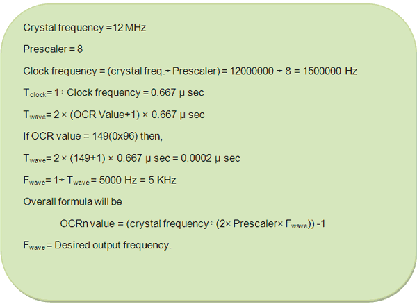
Equation For Frequency Calculation of Square Wave
Fig. 5: Equation For Frequency Calculation of Square Wave
Programming steps:
1. Select CTC mode by programming WGM0 [1:0] bit.
2. Program COM0 [1:0] bits and select “toggle OC0 if compare match”.
3. Set OC0 (PB3) pin as output pin.
4. Set OCIE0 bit of TIMSK register.
5. Enable global interrupt by “sei ()” command.
 
Circuit description:
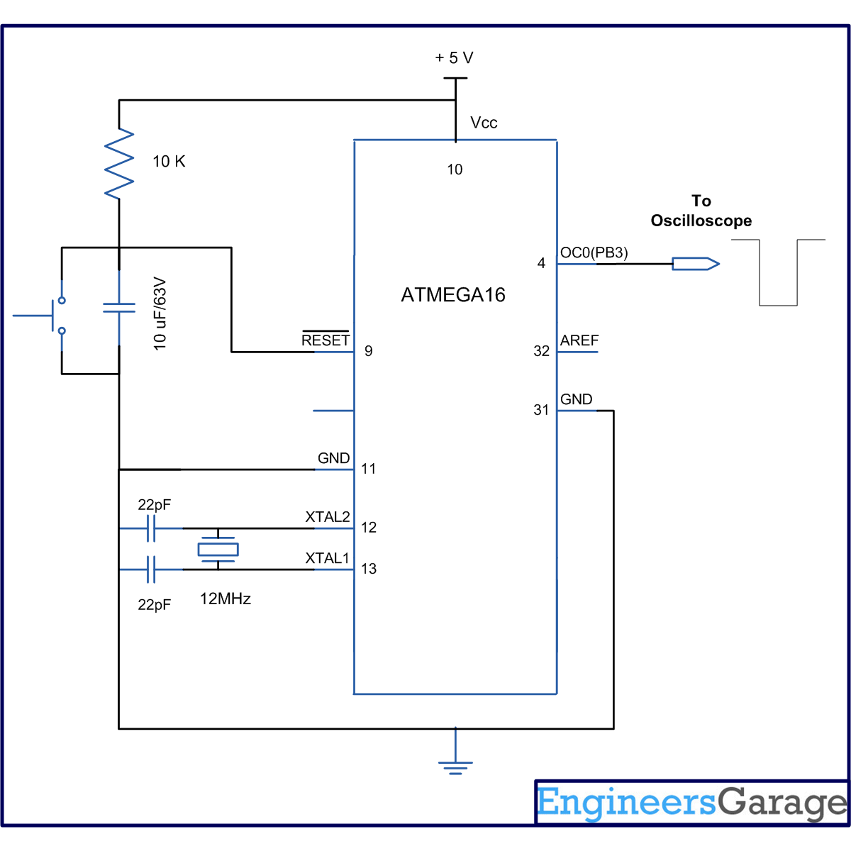
The connection of ATmega16 for this experiment is shown in circuit diagram. Since timer0 is used, hence the OC0 pin is connected to C.R.O to observe wave form. 
 
Output wave form:

The following picture shows the output wave form which is received on CRO. The measured frequency of wave is 5 KHz.
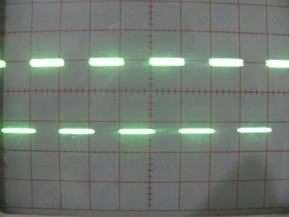
Output Square waveform on CRO using AVR Timer

Fig. 6: Output Square waveform on CRO using AVR Timer


Project Source Code

###


// Program to Generate waveform using AVR Microcontroller (Atmega16) Timers
#include<avr/io.h>
#include<util/delay.h>
#include<avr/interrupt.h>
void t0_init(void);
 
#define FREQ 12000000 // crsytal freqeuncy
#define PRECSALER 8
#define F_OUT 5000 // output frequency
#define OCR0_VALUE ((((FREQ/2)/PRECSALER)/F_OUT)-1)  
int main()
{
t0_init(); // timer initialize
sei(); // enable global interrupts
while(1);
}
 
void t0_init()
{
// WGM0[1:0]= 10, for CTC mode
// COM0[1:0]= 01, to toggle OC0 on compare match
// CS0[2:0] =010. for prescaler 8
 
TCCR0=(1<<WGM01)|(1<<COM00)|(1<<CS01);
DDRB|=(1<<PB3); // select as output pin 
TIMSK|=(1<<OCIE0); //enable output compare interrupt
}
 
ISR(TIMER0_COMP_vect) // interrupt subroutine
{
OCR0=(uint8_t)OCR0_VALUE; //put OCR value
}
 

###


Circuit Diagrams

Circuit-Diagram-of-Waveform-Generation-using-AVR-Microcontroller-Atmega16-Timers

Project Components

  • ATmega16

Project Video


Filed Under: AVR Microcontroller
Tagged With: atmega16, avr, microcontroller, timer, waveform generation
 

Questions related to this article?
👉Ask and discuss on Electro-Tech-Online.com and EDAboard.com forums.


Tell Us What You Think!! Cancel reply

You must be logged in to post a comment.

HAVE A QUESTION?

Have a technical question about an article or other engineering questions? Check out our engineering forums EDABoard.com and Electro-Tech-Online.com where you can get those questions asked and answered by your peers!


Featured Tutorials

  • Designing Gate Driver Circuit and Switching Mechanism for Modified Sine Wave Inverter – (Part 9/17)
  • Completing Modified Sine Wave Inverter Design with Full Bridge Circuit and Step Up Transformer – (Part 10/17)
  • Designing an Offline UPS – Part (12 /17)
  • How to reduce Switching Time of a Relay – (Part 15/17)
  • Testing MOSFET – (Part 16/17)
  • Driving High Side MOSFET using Bootstrap Circuitry – (Part 17/17)

Stay Up To Date

Newsletter Signup

Sign up and receive our weekly newsletter for latest Tech articles, Electronics Projects, Tutorial series and other insightful tech content.

EE Training Center Classrooms

EE Classrooms

Recent Articles

  • New automotive radar sensor enables reliable in-cabin monitoring system
  • TI breaks ground on 300-mm semiconductor wafer-fabrication plants in Texas
  • New wireless AR Smart Viewer reference design
  • Infineon launches scalable and wireless charging platform with configurable controllers
  • First single-core MPU with MIPI CSI-2 camera interface and audio

Most Popular

5G 555 timer circuit 8051 ai Arduino atmega16 automotive avr dc motor display Electronic Part Electronic Parts Fujitsu ic infineontechnologies integratedcircuit Intel IoT ir lcd ldr led maximintegratedproducts microchip microchiptechnology Microchip Technology microcontroller microcontrollers mosfet motor powermanagement Raspberry Pi remote renesaselectronics renesaselectronicscorporation Research samsung semiconductor sensor software STMicroelectronics switch Technology vishayintertechnology wireless

RSS EDABOARD.com Discussions

  • MOSFET ORing circuit simulation (LTspice)
  • A circuit that can adjust a resistance and probing a voltage node
  • MOSFET current control
  • MAX2771 digital output processing
  • request for a good manual on rectangular waveguide feeding network

RSS Electro-Tech-Online.com Discussions

  • Multistage BJT amplifier
  • Ampro 16mm Stylist projector woes.
  • Need help using a common power supply for two devices
  • NXP i.MX8 board vs Raspberry Pi?
  • Help me to start 24V BLDC (Star winding)
Engineers Garage
  • Analog IC TIps
  • Connector Tips
  • DesignFast
  • EDABoard Forums
  • EE World Online
  • Electro-Tech-Online Forums
  • Microcontroller Tips
  • Power Electronic Tips
  • Sensor Tips
  • Test and Measurement Tips
  • 5G Technology World
  • About Us
  • Contact Us
  • Advertise

Copyright © 2022 WTWH Media LLC. All Rights Reserved. The material on this site may not be reproduced, distributed, transmitted, cached or otherwise used, except with the prior written permission of WTWH Media
Privacy Policy | Advertising | About Us

Search Engineers Garage

  • Projects and Tutorials
    • Electronic Projects
      • 8051
      • Arduino
      • ARM
      • AVR
      • PIC
      • Raspberry pi
      • STM32
    • Tutorials
    • Circuit Design
    • Project Videos
    • Components
  • Articles
    • Tech Articles
    • Insight
    • Invention Stories
    • How to
    • What Is
  • News
    • Electronic Products News
    • DIY Reviews
    • Guest Post
  • Forums
    • EDABoard.com
    • Electro-Tech-Online
    • EG Forum Archive
  • Digi-Key Store
    • Cables, Wires
    • Connectors, Interconnect
    • Discrete
    • Electromechanical
    • Embedded Computers
    • Enclosures, Hardware, Office
    • Integrated Circuits (ICs)
    • Isolators
    • LED/Optoelectronics
    • Passive
    • Power, Circuit Protection
    • Programmers
    • RF, Wireless
    • Semiconductors
    • Sensors, Transducers
    • Test Products
    • Tools
  • EE Resources
    • DesignFast
    • LEAP Awards
    • Oscilloscope Product Finder
    • White Papers
    • Webinars
  • EE Learning Center
  • Women in Engineering