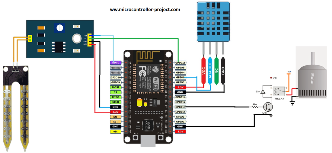
Project circuit
- DHT-11 Temperature and humidity sensor.
- Arduino soil and moisture level sensor.
- Nodemcu esp8266-12e WiFi module.
DHT-11 is a one wire digital temperature and humidity sensor. It can measure temperature from 0 degree Celsius to 50 degree Celsius with 2% margin of error. It can measure humidity levels between 20 to 80% with 5% margin of error. It requires 3 to 5 volts for its operation. I have an another and simple tutorial on interfacing DHT-11 with nodemcu wifi module you can learn more from that tutorial. Click the button below to learn more
Nodemcu works on 3.3 volts TTL logic. Its I/O pins also provides 3.3 volts as output. Relays normally needs 5 volts to 12 volts for proper activation of coils. 3.3 volts are not enough to activate the relay coils, alternatively drive the motor/pump. In order to tackle this i connected a NPN transistor with relay and controlled it base with the output of nodemcu digital pin. Now nodemcu 3.3 volt digital pin can drive a 12 volt relay. When digital pin is high motor starts and when it is made low motor will stop. I also have an another tutorial on interfacing relays with nodemcu and controlling heavy loads. Click the below button to learn more.
Project Circuit
Note: The ground of transistor must be grounded with the nodemcu ground and also with the source power supply Vs. Vs is external power supply to transistor to drive the relay. Vs depends on the relay you are using if its 12 volt relay. Then Vs must be a 12 volt power supply.
Connect the ground of the motor or pump with the power supply ground if its a dc pump. Connect the anode + lead of power to NO(normally open) pin of relay. Connect the com(common) pin of relay with the anode of motor. If pump is working on alternating 110 or 220 volts connect one lead of pump directly to one end of the power rail and NC contact of relay to another line of rail and comm of relay to second lead of pump.
const char* ssid = “Your SSID”;
const char* password = “Your Wifi Password”;
One thing to take care of. Both the client and server must be on the same network or in other words they must be connected to same WiFi. If they are not on same network their will be no communication between the client and server. So please be sure both are no the same network.
The headings and buttons above in code are due to the HTML code in the arduino ide. They are visible above because you are viewing it in a browser.
|
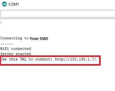
Just make the circuit and upload the code in nodemcu. After uploading the code enter the arduino serial monitor from arduino ide. You will see nodemcu rebooting. First connecting to your WiFi router. Then starting the server. After server start up it will show a web address. This web address is the address of the web page on which user can see the smart garden status and weather update. The web address will be some thing like on the right side. User have to enter this IP in browser of his desktop laptop mobile etc to load the status web page.
|
|
Web page also contains three buttons. Pressing the update button will update the readings displayed on page. Two other buttons turn off and on motor/pump manually. You can turn motor on and off through the web page.

Filed Under: ESP8266., Microcontroller Projects

Questions related to this article?
👉Ask and discuss on Electro-Tech-Online.com and EDAboard.com forums.
Tell Us What You Think!!
You must be logged in to post a comment.