Engineers Garage

  • Projects and Tutorials
    • Electronic Projects
      • 8051
      • Arduino
      • ARM
      • AVR
      • PIC
      • Raspberry pi
      • STM32
    • Tutorials
    • Circuit Design
    • Project Videos
    • Components
  • Articles
    • Tech Articles
    • Insight
    • Invention Stories
    • How to
    • What Is
  • News
    • Electronic Products News
    • DIY Reviews
    • Guest Post
  • Forums
    • EDABoard.com
    • Electro-Tech-Online
    • EG Forum Archive
  • Digi-Key Store
    • Cables, Wires
    • Connectors, Interconnect
    • Discrete
    • Electromechanical
    • Embedded Computers
    • Enclosures, Hardware, Office
    • Integrated Circuits (ICs)
    • Isolators
    • LED/Optoelectronics
    • Passive
    • Power, Circuit Protection
    • Programmers
    • RF, Wireless
    • Semiconductors
    • Sensors, Transducers
    • Test Products
    • Tools
  • EE Resources
    • DesignFast
    • LEAP Awards
    • Oscilloscope Product Finder
    • White Papers
    • Webinars
  • EE Learning Center
  • Women in Engineering

Web-Cam controller in VC++

By Ashutosh Bhatt

This is the most amazing and commercially viable project in which the web-cam attached to your computer will move in all four direction up-down and left-right with the help of your fingertips.

The software written in VC++ will control two different AC motors with the help of computer mouse. The forward and reverse motion of these motors will move web-cam up-down or left-right depending upon once choice. There are two modes to move camera in all four directions. 1) Auto and  (2) manual. In auto mode the camera moves left-right-up-down in a user program sequence while in manual mode it will move depending upon user command.  

General Description:-

There are three basic parts of project. (1) mechanical (2) hardware and (3) software.

Mechanical part is camera unit which consist of camera lens, two AC motors with given specifications and internal mechanism to rotate lens. The specifications of motor are

Motor type: – AC reversible motor 

Max applied voltage: – 230 VAC

Max rated RPM: – 5 RPM @ 230 VAC

Hardware part is AC motor driving circuit attached to LPT port of PC that will switch the supply given to motor and move it in a proper way

Software part is the actual interface between user and camera that will generate various signals through LPT and rotate two AC motors.

Note:-mechanical part is ready-made and available in market so we shall not discuss about it in deep

 Hardware & Software

Hardware Section: –

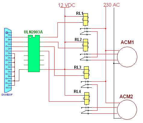
The circuit is designed to rotate both AC motors in either direction. For each motor we have two relays one for to turn ON or OFF the motor and second for changing direction. So four change over (C/O) relays are connected to LPT pins D0-D3 through current driver chip ULN2003A. All the relays are 12 VDC, 300 ohm (sugar cube type, PCB mount). One of the coil terminal of all the relays are shorted and connected to 12 V supply. The second terminal is connected to output of ULN chip. The relay contacts (C, NC, NO) are connected as shown in figure in Circuit Diagram Tab1. 

Here relays RL1 and RL3 are to turn ON / OFF the motors and RL2 and RL4 are for direction change. The ACM1 is used to move camera left and right while ACM2 moves camera up and down. So by switching these relays the camera will move in all four directions. The table given below will give you the idea that how a software can move the camera using LPT port

Relay(s)

Data pin(s)

Camera movement

Hex number

RL1

D0

Left to right

01h

RL1 & RL2

D0-D1

Right to left

03h

RL3

D2

Bottom to top

04h

RL3 & RL4

D2-D3

Top to bottom

0Ch


Software section:-

Software of VC Based Camera

As illustrated first there are two modes auto and manual, so in auto mode the software moves camera in pre programmed sequence and in manual mode the user (operator) can move the camera from keyboard or mouse. The application window look like this.

There are two group boxes, seven buttons and two check boxes. Here are there settings

Item

Property

Setting

Group box 1

ID

IDC_AUTO

Group box 2

ID

IDC_MAN

Button 1

ID

IDC_UP

Caption

UP

Button 2

ID

IDC_DWN

Caption

DOWN

Button 3

ID

IDC_LEFT

Caption

LEFT

Button 4

ID

IDC_RGHT

Caption

RIGHT

Button 5

ID

IDC_XIT

Caption

EXIT

Button 6

ID

IDC_ON

Caption

ON

Button 7

ID

IDC_OFF

Caption

OFF

Check box 1

ID

IDC_CHECK1

Caption

Enable

Check box 2

ID

IDC_CHECK2

Caption

Enable

After completing design now we have to attach code with these buttons. We have two enable buttons here so only one of the mode will be enable at a time. As you enable one mode second will be disabled. In manual mode all the given four buttons will send the hex number given in above table to LPT port address that is 0378 so that the particular relay get energized and it will rotate the motor.

The automatic mode is somehow different. The movement of camera is preprogrammed. The camera moves 150 deg. Left to right and 150 deg.  Top to bottom. Now as the motor is of 5 RPM means it rotates 1800 deg. In 60 sec. So in 1 sec motor rotates 30 deg. Thus to complete 150 deg it needs 5 sec.

Now the movement is divided in 6 steps

  1. Left to right means 5 sec (01h)
  2. Right to middle means 2.5 sec (03h)
  3. Middle to top again 2.5 sec (04h)
  4. Top to bottom. 5 sec (0Ch)
  5. Bottom to middle. 2.5 sec (04h)
  6. Middle to left again 2.5 sec (03h) and this cycle repeats

So for this we have used one counter that will count at an interval of every 0.5 sec. Total cycle time is 20 sec means the counter counts up to 40. The program assumes that when auto mode is enabled the cameras is at left most position


Circuit Diagrams

webcam-1


Filed Under: Circuit Design, Electronic Projects
Tagged With: computer, vc++, webcam
 

Questions related to this article?
👉Ask and discuss on EDAboard.com and Electro-Tech-Online.com forums.


Tell Us What You Think!! Cancel reply

You must be logged in to post a comment.

HAVE A QUESTION?

Have a technical question about an article or other engineering questions? Check out our engineering forums EDABoard.com and Electro-Tech-Online.com where you can get those questions asked and answered by your peers!


Featured Tutorials

  • Designing Gate Driver Circuit and Switching Mechanism for Modified Sine Wave Inverter – (Part 9/17)
  • Completing Modified Sine Wave Inverter Design with Full Bridge Circuit and Step Up Transformer – (Part 10/17)
  • Designing an Offline UPS – Part (12 /17)
  • How to reduce Switching Time of a Relay – (Part 15/17)
  • Testing MOSFET – (Part 16/17)
  • Driving High Side MOSFET using Bootstrap Circuitry – (Part 17/17)

Stay Up To Date

Newsletter Signup

Sign up and receive our weekly newsletter for latest Tech articles, Electronics Projects, Tutorial series and other insightful tech content.

EE Training Center Classrooms

EE Classrooms

Recent Articles

  • Renesas to demonstrate first working silicon based on the Arm Cortex-M85 processor
  • STMicroelectronics releases first automotive IMU with embedded machine learning
  • Infineon offers DC-DC controller for full LED headlamps without a microcontroller
  • Vishay launches new high-precision, thin-film wraparound chip resistor
  • STMicroelectronics’ common-mode filters ensure signal integrity in serial interfaces

Most Popular

5G 555 timer circuit 8051 ai Arduino atmega16 automotive avr dc motor display Electronic Part Electronic Parts Fujitsu ic infineontechnologies integratedcircuit Intel IoT ir lcd ldr led maximintegratedproducts microchip microchiptechnology Microchip Technology microcontroller microcontrollers mosfet motor powermanagement Raspberry Pi remote renesaselectronics renesaselectronicscorporation Research samsung semiconductor sensor software STMicroelectronics switch Technology vishayintertechnology wireless

RSS EDABOARD.com Discussions

  • Temperature sensor readout
  • Capacitive Switches
  • CSI-2 FIFO or Line buffer?
  • What is the function of the long stub?
  • Circuit Performance Exploration

RSS Electro-Tech-Online.com Discussions

  • software PWM
  • Opamp ciruit
  • Audio equalizer
  • Background of Members Here
  • SPI Questions
Engineers Garage
  • Analog IC TIps
  • Connector Tips
  • DesignFast
  • EDABoard Forums
  • EE World Online
  • Electro-Tech-Online Forums
  • Microcontroller Tips
  • Power Electronic Tips
  • Sensor Tips
  • Test and Measurement Tips
  • 5G Technology World
  • About Us
  • Contact Us
  • Advertise

Copyright © 2022 WTWH Media LLC. All Rights Reserved. The material on this site may not be reproduced, distributed, transmitted, cached or otherwise used, except with the prior written permission of WTWH Media
Privacy Policy | Advertising | About Us

Search Engineers Garage

  • Projects and Tutorials
    • Electronic Projects
      • 8051
      • Arduino
      • ARM
      • AVR
      • PIC
      • Raspberry pi
      • STM32
    • Tutorials
    • Circuit Design
    • Project Videos
    • Components
  • Articles
    • Tech Articles
    • Insight
    • Invention Stories
    • How to
    • What Is
  • News
    • Electronic Products News
    • DIY Reviews
    • Guest Post
  • Forums
    • EDABoard.com
    • Electro-Tech-Online
    • EG Forum Archive
  • Digi-Key Store
    • Cables, Wires
    • Connectors, Interconnect
    • Discrete
    • Electromechanical
    • Embedded Computers
    • Enclosures, Hardware, Office
    • Integrated Circuits (ICs)
    • Isolators
    • LED/Optoelectronics
    • Passive
    • Power, Circuit Protection
    • Programmers
    • RF, Wireless
    • Semiconductors
    • Sensors, Transducers
    • Test Products
    • Tools
  • EE Resources
    • DesignFast
    • LEAP Awards
    • Oscilloscope Product Finder
    • White Papers
    • Webinars
  • EE Learning Center
  • Women in Engineering