Electronic hardware filters can be classified into two types: active and passive.
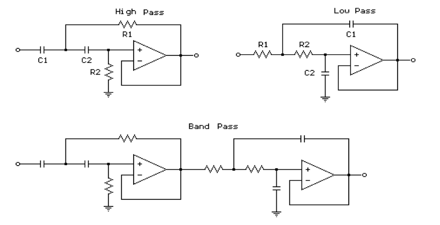
Active Filters: Filter circuits that consist of active components like transistors and op amps with passive components like resistors, capacitors, etc., are called active filters.
Passive filter: Filter circuits that consist of only a resistor, capacitor, and inductor and are tuned to resonate at a certain frequency, are called passive filters.
There are mainly four types of filters in electronics based on their frequency response, and they can be designed using active and passive components. These are low-pass, high-pass, bandpass, and band-reject filters (notch filters).
Low-pass filter
A filter that provides a constant output from DC up to a cutoff frequency and then passes no signal above that frequency is called an ideal low-pass filter.
The ratio of output voltage to the input voltage is called the voltage gain, which is constant over a frequency range from zero to cutoff frequency. Hence the output will be available faithfully from zero to cutoff frequency with a constant gain. The frequencies between zero to cutoff frequency are called passband frequencies, while the frequencies above cutoff frequency are called stopband frequencies.
In an ideal low-pass filter, low frequencies are in the pass band, and higher frequencies are in the stop band. A low-pass filter attenuates high frequencies and passes low-frequency components from a signal passing through a low-pass filter circuit.
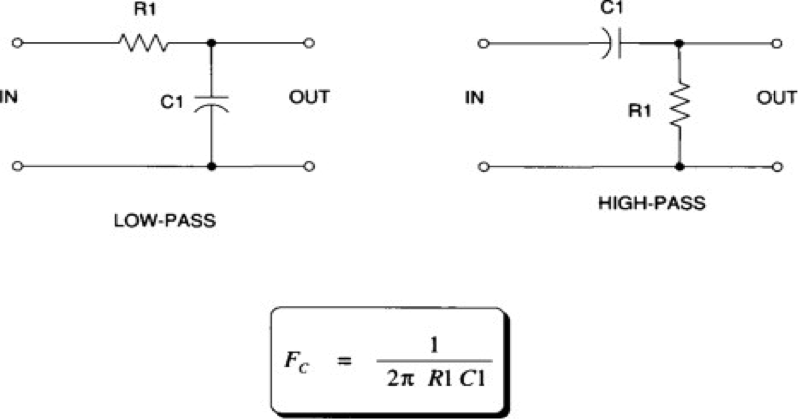
First-order analog filters can be designed by using a series resistor and a shunt capacitor or a series inductor and a shunt resistor.
…where Input Signal —> Low-pass filter —> Output signal (attenuated low frequencies)
For example, a signal has a frequency band of 100 MHz, and we need a signal of below 50 MHz band frequency. In this case, we need a low-pass filter that will attenuate the other frequency band that we don’t need. In power lines, a low-pass filter is used as an EMI filter to reduce the ratio of frequency components.
High-pass filter
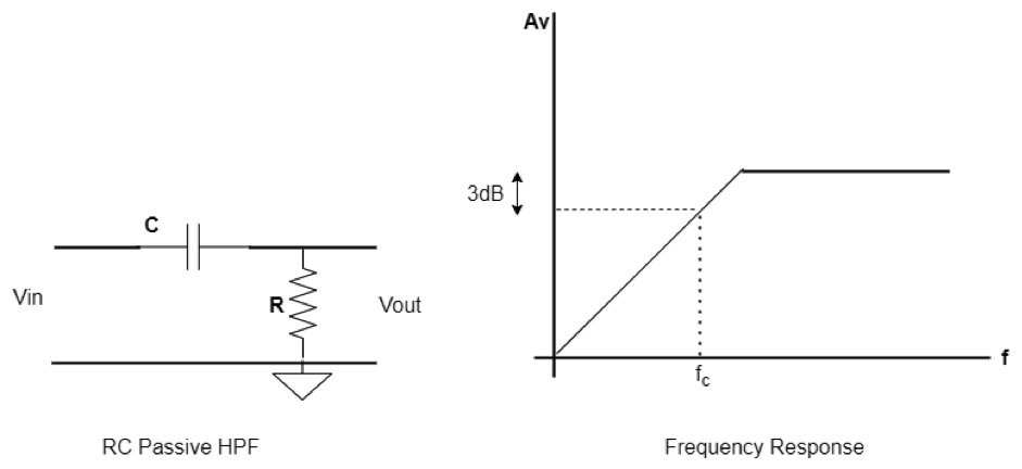
A filter that passes frequency band signals above cutoff frequency is called a high-pass filter. The high-pass filter has a zero gain to a frequency called the cutoff frequency, and above this frequency, the gain is constant. Hence, a signal of any frequency beyond cutoff is faithfully reproduced with a constant gain, and frequencies from zero to cutoff will be blocked.
The high-pass filter is the functional complement of the low-pass filter. In the high-pass filter, the low frequencies components are in the stop band, and the high frequencies components are in the pass band. That means a high-pass filter passes the high-frequency components and blocks low-frequency components of a signal while passing it through a high-pass filter. High-pass filters can be implemented by using a series capacitor and a shunt resistor or a series resistor and a shunt inductor.
…where, Input Signal —> High-pass filter —> Output signal (attenuated high frequencies)
If a signal has a frequency band of 50 MHz and we need a signal beyond the 30 MHz frequency band, then we need this type of filter that will stop the frequency band below 30 MHz and allow the frequency above 30 MHz in ideal cases. These filters are used in loudspeakers to remove low-level noise.
Bandpass filter
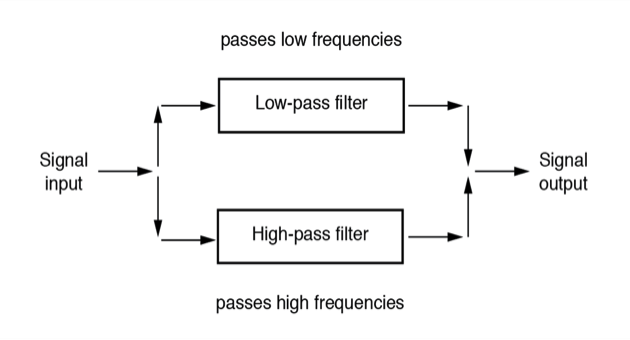
The cascaded version of a high-pass filter and low-pass filter is called a bandpass filter. The band pass filter passes a set of frequencies between a lower cutoff frequency and an upper cutoff frequency. Frequencies below a lower cutoff frequency and above a higher cutoff frequency are in the stop band. The ideal bandpass filter is shown in the figure below. A band pass filter passes a band of frequencies while attenuating other parts of frequencies (left and right) that are outside of the band of a signal.
…where, Input Signal —> Low-pass filter —> High-pass filter —>Output signal
If, for example, a signal consists of a frequency band of 200 MHz, and we need a signal that consists of a frequency band of above 50 MHz and below 100 MHz, then we need a band pass filter. One application of these filters is telephones or modern cell phones, given the audio side is roughly 250 Hz to 5Khz.
Band reject filter (Notch filter)
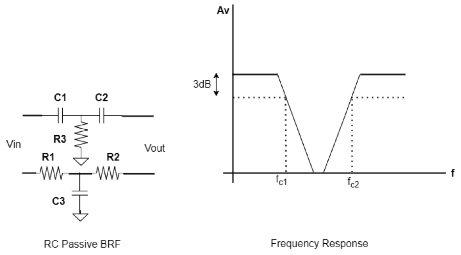
The complement of the bandpass filter is called band reject, which is also called a notch filter. In this filter, the frequencies below the lower cutoff frequency and above the higher cutoff frequency is in the passband. The frequencies between lower cutoff frequency and higher cutoff frequency come in the stop band. The figure below shows a notch response.
The idealized filters defined above cannot be built easily. There should be an instantaneous transition from pass band to stop band. But there is a transition region that is reduced by the designer by doing various order filter designs.
Suppose we have a signal that consists of a frequency band of 200 MHz, and we need a signal that consists of a frequency band of below 50 MHz and above 100 MHz. In this case, we need a band reject filter. An example is notch filters which are used in medical equipment to remove the 50 Hz hum.
This article reviewed basic hardware filters used in signal filtering, noise reduction, and removing undesired frequency components from an information signal.
You may also like:
Filed Under: Hardware Filters, Tutorials






Questions related to this article?
👉Ask and discuss on Electro-Tech-Online.com and EDAboard.com forums.
Tell Us What You Think!!
You must be logged in to post a comment.