A protection relay is a smart device that receives inputs like current, voltage, resistance, temperature, or even light, compares them to set points, and provides outputs such as visual feedback in the form of indicator lights and/or an alphanumeric display, communications, control warnings, alarms, and turning the power off and on. They are used for motor protection and ground fault protection in industrial settings. A regulating relay is a special class of protection relay that activates when an operating parameter deviates from preset limits.
This FAQ contrasts and compares traditional electrotechnical and solid-state protective relays, look at how layers of protective relays are used to protect zones in electricity transmission and distribution networks, then reviews the operation of ground fault and arc flash protective relays.
Protective relays can be based on electromechanical or solid-state relay technology. In lower-power applications, electromechanical designs have mostly been replaced by solid-state devices. But electromechanical relays continue to be used in high-power applications in electricity transmission and distribution systems. Microprocessor-based protective relays can detect small changes in parameters like voltage, current, resistance, or temperature that can be used to identify the early stages of a problem before it is severe enough to trip conventional protective devices like circuit breakers or fuses. A protection relay can detect the cause of a fault, such as overcurrent, overvoltage, or increases in temperature, that conventional protection devices cannot identify. And a protection relay can provide a variety of outputs, including local or remote alarms and visual indicators, and even shut down the equipment if the situation is severe enough (Figure 1).
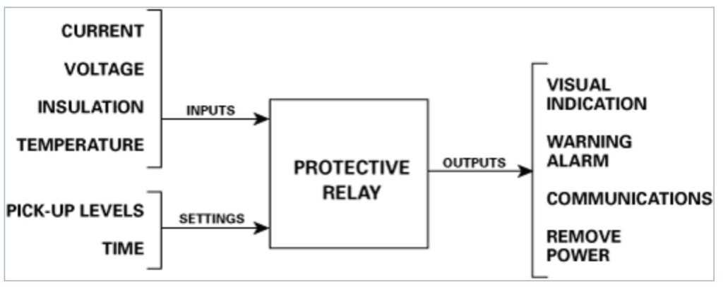
Figure 1: Protective relays can be designed to accept a variety of inputs and produce outputs based on fault settings or thresholds. (Image: Littelfuse)
In electrical engineering, especially in electricity transmission and distribution networks, a protective relay is used to trip a circuit breaker when a fault is detected. In these systems, protection needs to be provided against various conditions like overcurrent, overvoltage, reverse power flow, over-frequency, and under-frequency. While microprocessor-based protective relays are increasingly common throughout the utility industry, many electromechanical protective relays can still be found in electricity distribution networks (Figure 2).
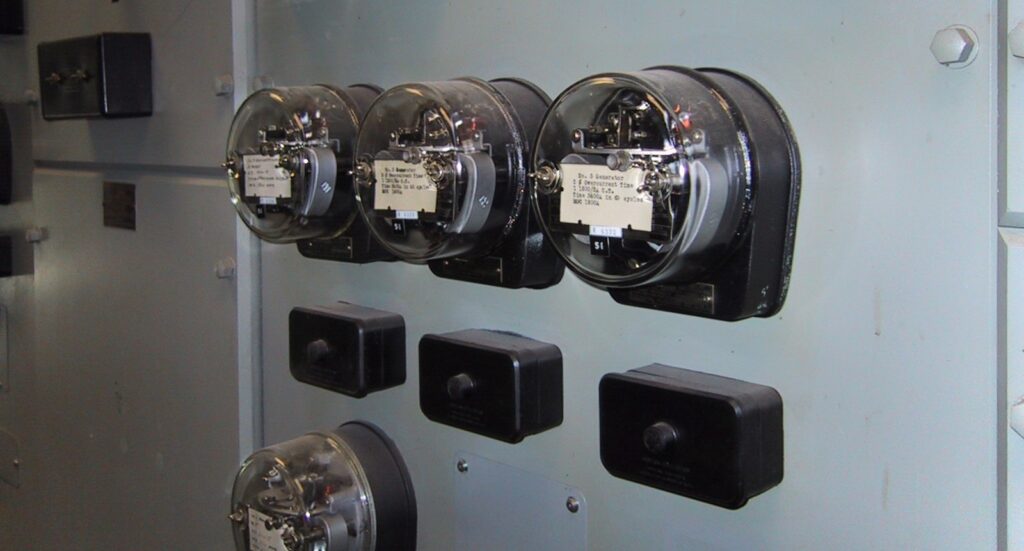
Figure 2: Electromechanical protective relays (glass enclosures) are still found in many electricity distribution networks. (Image: Wikipedia)
Electromechanical protective relays are different
Conventional electromechanical relays have fixed and relatively wide operating thresholds and times. Electromechanical protective relays operate by magnetic induction or attraction and have well-defined, adjustable, and selectable time and parametric operating entries. To achieve this improved performance, protection relays can employ arrays of induction disks, magnets, coils, phase-shifting networks, and other techniques. Protective relays are available with a range of architectures. Some respond to a simple magnitude of a parameter like voltage or current. Induction relays use two field coils to produce the product of two parameters, for example, current and voltage, and respond if the power level is too high. Multiple locks can be used to bias the relay using a separate circuit to control the sensitivity of its response.
Some protective relays have a permanent magnet in the magnetic circuit enabling the relay to respond to current in one direction differently from another direction. These are called polarized relays and can be used on DC circuits to detect reverse current in a generator. Polarized relays can be bistable and maintain a closed contact when no coil current is flowing and opening the contact when reverse current is present. The principle can be used with a polarizing winding connected to a reference voltage in AC circuits.
Protection zones
Protective relays in industrial and utility systems can be used to protect zones within the power system. These zones are usually based on functionality such as generators, motors, transformers, distribution feeders and buses, and transmission lines. When using protection relays, the overall system is divided into sections to provide “zones of protection” that define the system boundaries that the individual relays are required to protect.
For a higher level of protection, the zones can be defined to overlap, enabling multiple layers of protection to be provided to critical equipment. This architecture has a primary protective relay and one or more secondary protection devices. Overlapping and backup protection ensures that all devices remain protected in the event of multiple failures. Redundant protection relays can provide the same level of protection but require a larger number of devices (Figure 3).
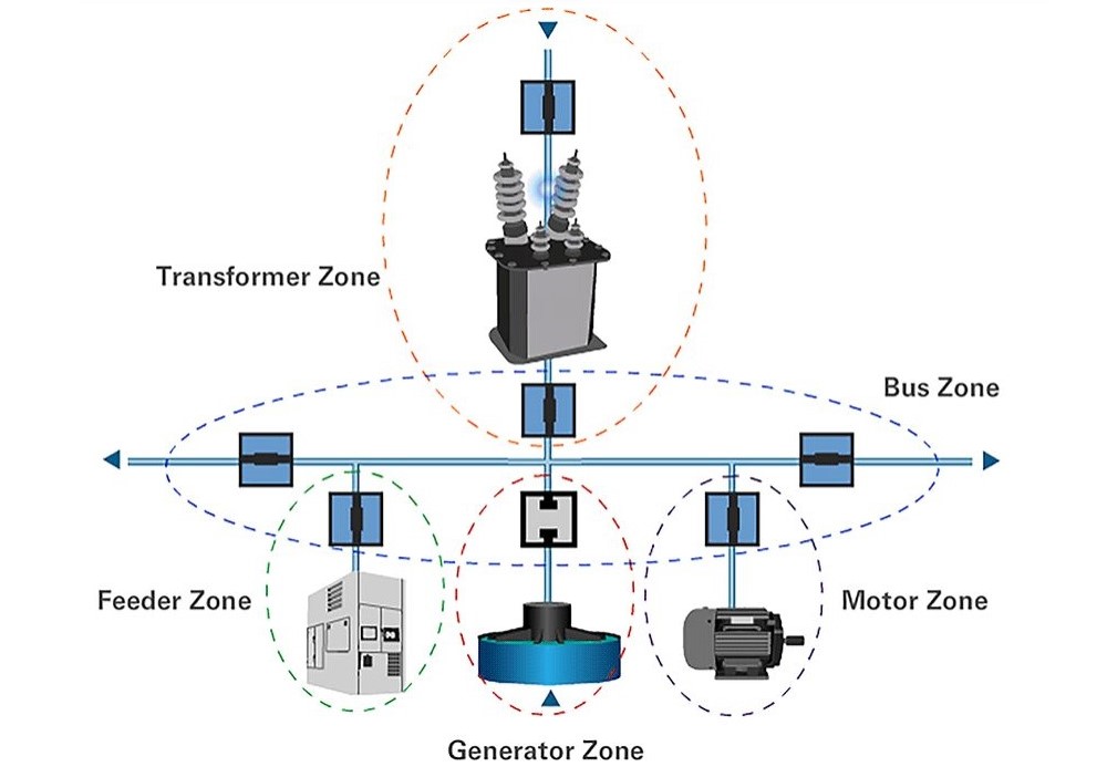
Figure 3: Multiple protection zones can be used in industrial installations to provide a higher level of protection. (Image: Eaton)
Ground fault relays
There are a variety of ground-fault protective devices, including residual-current devices (RCD), earth leakage circuit breakers (ELCB), ground-fault equipment protectors (GFEP), and ground-fault circuit interrupters (GFCI); their primary function is the protection of people and equipment against ground faults by interrupting/disconnecting the defective circuit.
In the U.S., GFCIs must comply with UL 943 and are designed to protect people. GFEPs (which include ground fault relays) must comply with UL 1053 and are designed for equipment protection. GFCIs have a sensitivity of 5 to 6 mA and can be subject to nuisance tripping if used to protect equipment like variable-speed motor drives. GFEPs have a sensitivity of 30 mA or higher and are resistant to nuisance tripping. GFEPs and ground fault relays (or sensors) are designed to sense low-magnitude ground faults. When the current magnitude and time reach a set point, a control system opens the relay to disconnect the circuit. Ground fault relays protect against low-level ground faults and must be used in coordination with fuses or circuit breakers that can protect against higher-magnitude ground faults.
Low-level ground fault protection is important since those faults will not trip circuit breakers or blow fuses but can cause major factory and industrial operations disruptions. A ground fault can damage equipment or cause a fire. Ground fault protection is used in water treatment plants, pumping systems, marine and mining environments, and in wash-down areas in industrial plants. Ground fault protection is a very specific activity it is not intended to:
- Prevent ground faults
- Protect operators from electrical shocks
- Protect from 3-phase, phase-to-phase or phase-to-neutral faults
An example of ground fault detection is to pass all the cables connected to a motor through the window of a ground fault current sensor. If there is no ground fault, all the currents will be balanced, and no current will be induced in the sensor. Unbalanced currents indicate the existence of a ground fault. The current differential will be measured by the current sensor and amplified for use in the control circuit. If the current exceeds the ground fault current set point, the ground fault relay will be turned on, disconnecting the motor. In some systems, the current sensor is directly connected to the ground fault relay.
Arc flash protection relays
An arc flash is the light and heat produced from an electric short-circuit arc. An arc flash can cause substantial damage to equipment, start a fire, or harm nearby personnel. Electrical arcs have incremental negative resistance as the temperature rises. As the arc gets hotter, its resistance drops, carrying more current. As the cycle continues, an arc flash can reach nearly 20,000 °C. Arc flash protection relays don’t prevent an arc flash but are used to reduce the energy in an arc flash rapidly.
By reducing the severity of the flash, an arc flash relay can reduce the personnel protective equipment (PPE) rating of an installation from a very dangerous level 4, requiring rubberized clothing that does not conduct electricity and other precautions to a more easily managed PPE level 2.
Instead of trying to measure increases in current flow, arc flash relays use optical sensors to “see” the flash more quickly. Arc-flash relays are microprocessor-based devices that can detect the onset of a flash as quickly as 125 μs. Once a flash is detected, a fast-switching can IGBT trip a circuit breaker in a few milliseconds and stop the flash before it becomes too severe (Figure 4). The rapid response time of an arc flash relay minimizes the possibility of extensive equipment damage and protects nearby personnel.
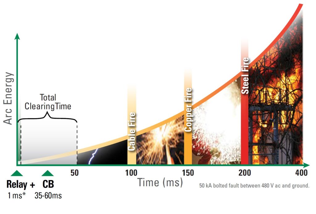
Figure 4: An arc flash protection relay can respond in milliseconds to quench a building arc and protect equipment and personnel. (Image: Littelfuse)
Summary
Protection relays are used to safeguard equipment and operators. They use parameters like current, voltage, resistance, temperature, or even light, to determine unsafe operating conditions and provide outputs like control warnings, alarms, and turning the power off. GFEPs are specialized ground fault detection devices designed specifically for protecting industrial equipment. Arc flash protection relays are designed to reduce the PPE rating of an installation and provide protection for both equipment and personnel.
References
Arc Flash, Wikipedia
Ground Fault Protection, Eaton
Improve safety and reliability with instant arc-flash detection, Littelfuse
Protective relay, Wikipedia
Protective relays & predictive diagnostics, Eaton
Understanding ground-fault protective devices, ABB
What is a protection relay? Littelfuse
You may also like:
Filed Under: What Is





Questions related to this article?
👉Ask and discuss on Electro-Tech-Online.com and EDAboard.com forums.
Tell Us What You Think!!
You must be logged in to post a comment.