 In industries, a large number of machines are deployed. Some machines may need to be kept on for longer periods while some may require to be switched off over a relatively shorter period due to an overheating problem or the operational requirement of the specific industrial process. There may also be a chance that the machines need to work in a specific time-based sequence to accomplish an industrial process. All such scenarios make the use of machines complicated and may require skilled supervision and guidance over the employed human resource. By automating the operation of machines through a centrally controlled console, the complicity of the above-mentioned procedures can be eased.
This project is a demonstration of similar automation using the wireless technology. In the project DC motors are used as loads connected to an Arduino Pro Mini board through L293D ICs. The Arduino board receives control signals from an RF remote built on 434 MHz RF module and provides the intelligence to control motors.
Control Signal 0x1 : Start each DC motor one after the other on an incremental delay of 1 second and Keep them rotating unless signal to stop them all is received. This is like on receiving the signal, first motors starts rotating, second motor starts rotating after 1 second with respect to the first, third motor starts rotating after 2 seconds with respect to second and so on.
Control Signal 0x2 : All motors start rotating on receiving the signal and rotate for three seconds then stop simultaneously.
Control Signal 0x4 : All motors start rotating on receiving the signal and rotate for three seconds then stop one after the other over a constant delay of 1 second from each other.
Control Signal 0x8 : Stop all motors immediately.
There are four motors used in the project to illustrate the wireless automation. This project can be used to control other loads as well by interfacing devices through a relay circuit instead of L293D motor driver controller circuit for DC motors.

Fig. 1: Prototype of Transmitter Side of RF based Wireless Automation and Control
Components Required
| Sr. No | Components Required | Quantity |
|---|---|---|
| 1 | RF Tx module(434Mhz) | 1 |
| 2 | RF Rx Module(434 Mhz) | 1 |
| 3 | HT12E | 1 |
| 4 | HT 12D | 1 |
| 5 | LED | 1 |
| 6 | Resistor – 1KΩ (Quarter watt) | 12 |
| 7 | Resistor – 1MΩ (Quarter watt) | 1 |
| 8 | Resistor – 50KΩ (Quarter watt) | 1 |
| 9 | Pushbutton | 4 |
| 10 | DC Motor | 4 |
| 11 | Battery – 9V | 1 |
| 12 | Battery – 12V | 1 |
| 13 | L293D | 2 |
| 14 | Opto- coupler(MCT12E827Q) | 8 |
| 15 | Breadboard | 3 |
| 16 | Arduino development board | 1 |
| 17 | Connecting wires | – |

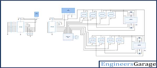
Fig. 2: Block Diagram of RF based Wireless Automation and Control
Circuit Connections
There are two circuits in the project – one is the remote control circuit and the other is DC motor control circuit. The remote control circuit is a 434 MHz RF transmitter. The transmitter module has the basic setup configuration with RF transmitter connected to an HT12E encoder IC and an antenna of standard size connected at the pin 4 of transmitter. The address byte of the HT12E encoder is set to 0x00 by hard-wiring all the address bits to ground. The pin 14 is also hard-wired to ground to enable uninterrupted transmission. A set of four push-to-on switches is connected to the data pins of HT12E through VCC. The data pins are by default connected to ground. Hence, the default control signal transmitting without interruption is 0x0. Learn about the basic setup of RF transmitter and receiver.
The DC motor control circuit has the Arduino Pro Mini as the central processing unit. An RF receiver is used to receive the control signals from the transmitter. The RF receiver has the basic setup and configuration, with RF receiver fetching the signal from an antenna connected at pin 8 and HT12D decoder IC’s pin 14 connected to pin 2 (serial output) of the receiver. All the address bits of HT12D are grounded to match the 0x00 address byte of the transmitter and enable pairing of the modules. The data pins D0 to D3 of the HT12D are connected to pin 13 to10 of the Arduino Pro Mini.

Fig. 3: Prototype of Receiver side of RF based Wireless Automation and Control
The DC motors are connected to the Arduino by L293D IC and the pins of L293D are interfaced through the Arduino via opto-couplers
Learn more about remote controlling DC motors by RF module.
There are four motors controlled in the circuit. The control signal for motor 1, 2, 3 and 4 are output by pin 9 and 8, pin 7 and 6, pin 5 and 4, and pin 3 and 2 of the Arduino respectively. These pins are configured to digital output in the project code. Therefore, pin 9 and 8 of the Arduino board is connected to pin 7 and 2 of first L293D respectively via opto-couplers for which motor 1 is connected between pins 3 and 6 of the respective L293D. The pin 7 and 6 of the Arduino board is connected to pin 10 and 15 of first L293D respectively via opto-couplers for which motor 2 is connected between pins 11 and 14 of the respective L293D. The pin 5 and 4 of the Arduino board is connected to pin 7 and 2 of second L293D respectively via opto-couplers for which motor 3 is connected between pins 3 and 6 of the respective L293D. The pin 3 and 2 of the Arduino board is connected to pin 10 and 15 of second L293D respectively via opto-couplers for which motor 4 is connected between pins 11 and 14 of the respective L293D.
How the Circuit Works?
In the remote controller circuit, the default signal transmitted uninterrupted is 0x0. The transmission signal can be changed by pressing the push-to-on switches connected at the encoder IC. On pressing any switch, the respective data pin goes high and the transmission nibble is altered accordingly.
At the motor controller circuit, the control signal is detected and passed to the Arduino board. On switching on the controller circuit, the project code is initialized to configure data pins connected to HT12D as digital input while data pins connected to L293D ICs via opto-couplers as digital output. The Arduino Pro Mini is programmed to detect the received control signals and accordingly set the output pins LOW or HIGH to control the motors. The L293D IC pins has the same status as of the Arduino pin connected to them via opto-couplers.
The L293D IC controls the DC Motors according to the following truth tables – :
| Pin 1/Enable Inputs 1 and 2 | Pin 2/Input 1 | Pin 7/Input 2 | Motor Connected between Pins 3 and 6)Function |
|---|---|---|---|
| LOW | N/A | N/A | Motor Stops |
| HIGH | HIGH | HIGH | Motor Stops |
| HIGH | LOW | LOW | Motor Stops |
| HIGH | HIGH | LOW | Motor Turns Anti-Clockwise |
| HIGH | LOW | HIGH | Motor Turns Clockwise |
| Pin 9/Enable Inputs 3 and 4 | Pin 10/Input 3 | Pin 15/Input 4 | Motor Connected between Pins 11 and 14) Function |
|---|---|---|---|
| LOW | N/A | N/A | Motor Stops |
| HIGH | HIGH | HIGH | Motor Stops |
| HIGH | LOW | LOW | Motor Stops |
| HIGH | HIGH | LOW | Motor Turns Anti-Clockwise |
| HIGH | LOW | HIGH | Motor Turns Clockwise |
Fig. 4: Image of of RF based Wireless Automation and Control
Learn more about controlling DC motors using RF Module
On pressing switch connected to D0 of the HT12E IC, 0x1 is transmitted over the system. On detecting 0x1 through the program code, the Arduino outputs a sequence of LOW and HIGH bits to the pins configured digital output, in the following time-based sequence from left to right.
|
Arduino Pin
|
L293D(1) Pin | L293D (2)Pin | Status | Delay | Status | Delay | Status | Delay | Status | Delay |
|---|---|---|---|---|---|---|---|---|---|---|
| 9 | 7 | N/A | LOW | 1 Sec | LOW | 2 Sec | LOW | 3 Sec | LOW | 4 Sec |
| 8 | 2 | N/A | HIGH | HIGH | HIGH | HIGH | ||||
| 7 | 10 | N/A | LOW | LOW | LOW | LOW | ||||
| 6 | 15 | N/A | LOW | HIGH | HIGH | HIGH | ||||
| 5 | N/A | 7 | LOW | LOW | LOW | LOW | ||||
| 4 | N/A | 2 | LOW | LOW | HIGH | HIGH | ||||
| 3 | N/A | 10 | LOW | LOW | LOW | LOW | ||||
| 2 | N/A | 15 | LOW | LOW | LOW | HIG |
0X1 Control Sequence Table
Therefore, first only motor 1 controlled by pin 7 and 2 of L293D (1) starts rotating anti-clockwise. After a delay of 1 second, motor 2 controlled by pins 10 and 15 of L293D (1) starts rotating while motor 1 keeps in rotation. Then after a delay of 2 seconds, motor 3 controlled by pin 7 and 2 of L293D (2) also starts rotating. Finally, after a delay of 3 seconds, motor 4 controlled by pins 10 and 15 of L293D (2) too starts rotating. The digital outputs are latch-type and remains constant until new signal is output.
On pressing switch connected to D1 of the HT12E IC, 0x2 is transmitted over the system. On detecting 0x2 through the program code, the Arduino outputs a sequence of LOW and HIGH bits to the pins configured digital output, in the following time-based sequence from left to right.
| Arduino Pin | L293D(1) Pin | L293D (2)Pin | Status | Delay | Status | Delay |
|---|---|---|---|---|---|---|
| 9 | 7 | N/A | LOW | 3 Sec | LOW | 1 Sec |
| 8 | 2 | N/A | HIGH | LOW | ||
| 7 | 10 | N/A | LOW | LOW | ||
| 6 | 15 | N/A | HIGH | LOW | ||
| 5 | N/A | 7 | LOW | LOW | ||
| 4 | N/A | 2 | HIGH | LOW | ||
| 3 | N/A | 10 | LOW | LOW | ||
| 2 | N/A | 15 | HIGH | LOW |
On pressing switch connected to D2 of the HT12E IC, 0x4 is transmitted over the system. On detecting 0x4 through the program code, the Arduino outputs a sequence of LOW and HIGH bits to the pins configured digital output, in the following time-based sequence from left to right.
| Arduino Pin | L293D(1) Pin | L293D(2) Pin | Status | Delay | Status | Delay | Status | Delay | Status | Delay | Status | Delay |
|---|---|---|---|---|---|---|---|---|---|---|---|---|
| 9 | 7 | N/A | LOW |
3 Sec |
LOW | 1 Sec | LOW | LOW | LOW | 1 Sec | ||
| 8 | 2 | N/A | HIGH | LOW | LOW | LOW | LOW | |||||
| 7 | 10 | N/A | LOW | LOW | LOW | LOW | LOW | |||||
| 6 | 15 | N/A | HIGH | HIGH | LOW | LOW | LOW | |||||
| 5 | N/A | 7 | LOW | LOW | LOW | LOW | LOW | |||||
| 4 | N/A | 2 | HIGH | LOW | HIGH | LOW | LOW | |||||
| 3 | N/A | 10 | LOW | LOW | LOW | LOW | LOW | |||||
| 2 | N/A | 15 | HIGH | LOW | LOW | HIGH | LOW |
0X4 Control Sequence Table
Therefore, on receiving 0x4, all motors starts rotating and keeps rotating for 3 seconds. Later motor 1 is stopped by setting both of its control pins to LOW. After a delay of 1 second, motor 2 is also stopped by setting both of its control pins to LOW. Similarly other two motors are also stopped one after the other on a delay of 1 second.
On pressing switch connected to D3 of the HT12E IC, 0x8 is transmitted over the system. On detecting 0x8 through the program code, the Arduino outputs a sequence of LOW and HIGH bits to the pins configured digital output, in the following time-based sequence from left to right.
| Arduino Pin | L293D(1) Pin | L293D (2)Pin | Status |
|---|---|---|---|
| 9 | 7 | N/A | LOW |
| 8 | 2 | N/A | LOW |
| 7 | 10 | N/A | LOW |
| 6 | 15 | N/A | LOW |
| 5 | N/A | 7 | LOW |
| 4 | N/A | 2 | LOW |
| 3 | N/A | 10 | LOW |
| 2 | N/A | 15 | LOW |
0X8 Control Sequence Table
Therefore on receiving 0x8, both the control pins for all motors are set to LOW and all the motors are stopped immediately.
Programming Guide
On switching on the motor controller circuit, first the Arduino loads the required standard libraries and runs the initialization code. In the initialization code, variables are assigned to the Arduino pins and they are set to digital input or output in a setup() function. The baud rate is set to 9600 bits per second using the Serial.begin() function of the Wire Library.
Otherwise, if the 0x2 signal is detected by checking tx2 variable, if it is HIGH, a sequence of LOW and HIGH bits is sent to the output pins as mentioned in 0x2 Control Sequence Table
Similarly, 0x4 nibble is detected by verifying the status of tx3 variable and a sequence of LOW and HIGH bits as mentioned in 0x4 Control Sequence Table is implemented via calls to digitalWrite() function} else if (Tx3 == HIGH){
Finally, 0x8 control signal is detected by verifying the status of tx4 variable and a sequence of LOW and HIGH bits as mentioned in 0x8 Control Sequence Table is passed to the output pins} else if (Tx4 == HIGH ){
The if-else-if logic tests the conditions top to down i.e. first it tries to detect 0x1, if it is not true, it skips to detect 0x2 and so forth. Therefore, if any switch connected to data pin of lower bit denomination of the encoder IC like D1in contrast to D2 or D3 of the encoder IC is left pressed, though a different control signal like D1 and D2 both are pressed and 0x6 is transmitted, the if-else logic will implement the lighting pattern corresponding to lower bit denomination (as it is tested before the other in the code) and will skip the test condition.
Project Source Code
###
//decoder 10,11,12,13 output pins connected to Arduino 10,11,12,13 digital pins as input. int tx1 = 6; int tx2 = 7; int tx3 = 8; int tx4 = 9; //decoder 10,11,12,13 output pins connected to Arduino 6,7,8,9 digital pins as input. int m11 = 2; int m12 = 3; int m21 = 4; int m22 = 5; int m31 = 10; int m32 = 11; int m41 = 12; int m42 = 13;void setup(){ pinMode(tx1,INPUT); pinMode(tx2,INPUT); pinMode(tx3,INPUT); // decoder output microcontroller reading as input. pinMode(tx4,INPUT); void setup(){ pinMode(tx1,INPUT); pinMode(tx2,INPUT); pinMode(tx3,INPUT); // decoder output microcontroller reading as input. pinMode(tx4,INPUT);void setup(){ pinMode(tx1,INPUT); pinMode(tx2,INPUT); pinMode(tx3,INPUT); // decoder output microcontroller reading as input. pinMode(tx4,INPUT); pinMode(m11,OUTPUT); pinMode(m12,OUTPUT); pinMode(m21,OUTPUT); // led's as output. pinMode(m22,OUTPUT); pinMode(m31,OUTPUT); pinMode(m32,OUTPUT); pinMode(m41,OUTPUT); // led's as output. pinMode(m42,OUTPUT); Serial.begin(9600); } void loop(){ // reading data and storing in a variable for further use. int Tx1 = digitalRead(tx1); int Tx2 = digitalRead(tx2); int Tx3 = digitalRead(tx3); int Tx4 = digitalRead(tx4); if (Tx1 == HIGH ){ digitalWrite(m11,LOW); digitalWrite(m12,HIGH); delay(1000); digitalWrite(m21,LOW); digitalWrite(m22,HIGH); delay(2000); digitalWrite(m31,LOW); digitalWrite(m32,HIGH); delay(3000); digitalWrite(m41,LOW); digitalWrite(m42,HIGH); delay(4000); } else if (Tx2 == HIGH){ digitalWrite(m11,LOW); digitalWrite(m12,HIGH); digitalWrite(m21,LOW); digitalWrite(m22,HIGH); digitalWrite(m31,LOW); digitalWrite(m32,HIGH); digitalWrite(m41,LOW); digitalWrite(m42,HIGH); delay(3000); digitalWrite(m11,LOW); digitalWrite(m12,LOW); digitalWrite(m21,LOW); digitalWrite(m22,LOW); digitalWrite(m31,LOW); digitalWrite(m32,LOW); digitalWrite(m41,LOW); digitalWrite(m42,LOW); delay(1000); } else if (Tx3 == HIGH){ digitalWrite(m11,LOW); digitalWrite(m12,HIGH); digitalWrite(m21,LOW); digitalWrite(m22,HIGH); digitalWrite(m31,LOW); digitalWrite(m32,HIGH); digitalWrite(m41,LOW); digitalWrite(m42,HIGH); delay(3000); digitalWrite(m11,LOW); digitalWrite(m12,LOW); delay(1000); digitalWrite(m21,LOW); digitalWrite(m22,LOW); delay(1000); digitalWrite(m31,LOW); digitalWrite(m32,LOW); delay(1000); digitalWrite(m41,LOW); digitalWrite(m42,LOW); delay(1000); } else if (Tx4 == HIGH ){ digitalWrite(m11,LOW); digitalWrite(m12,LOW); digitalWrite(m21,LOW); digitalWrite(m22,LOW); digitalWrite(m31,LOW); digitalWrite(m32,LOW); digitalWrite(m41,LOW); digitalWrite(m42,LOW); } }###
Circuit Diagrams
Project Video
Filed Under: Electronic Projects
Filed Under: Electronic Projects

Questions related to this article?
👉Ask and discuss on EDAboard.com and Electro-Tech-Online.com forums.
Tell Us What You Think!!
You must be logged in to post a comment.