CC2500 is wireless transmitter receiver developed by Texas instruments which is used in 2400-2483.5 MHz ISM/SRD band systems. In this project, the input present at PORTD of transmitter atmega8 is transmitted wirelessly to the PORTD of receiver atmega8. This project shows how to configure registers of CC2500, how to give commands to CC2500 and how to activate transmission or receiver mode of CC2500 via SPI interfacing with avr microcontroller. The CC2500 RF module is a low-cost 2.4 GHz transceiver used in very low power wireless applications. The RF transceiver is integrated with a highly configurable baseband modem. It support OOK, 2-FSK, GFSK, and MSK modulations. It works in voltage range of 1.8 – 3.6V. Two AA batteries are enough to power it. It has 30m range with onboard antenna. It is always used with microcontroller which support SPI communication.
Programming CC2500:
SPI interface: CC2500 is configured via a simple 4-wire SPI compatible interface (SI, SO, SCLK and CSn) where CC2500 is the slave and microcontroller (here atmega8) is used as master.
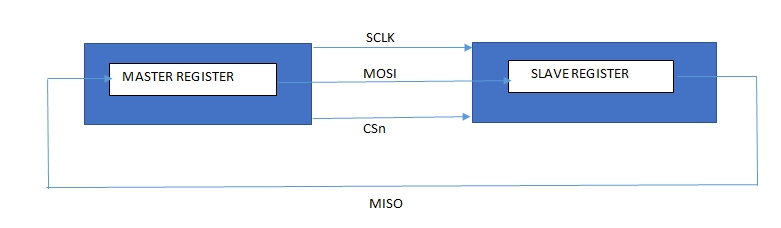
SPI interfacing
Register access and commands are given serially to CC2500 by atmega8 with spi interface. In SPI, master generate clock and chip select signal. SPI communication involves two shift registers. One in master and other in slave. Data is shifted from master to slave and slave to master in circular manner in synchronous with clock generated by master and at the end of shift operation, data in master register and slave register is exchanged.
In CC2500, all transfers on the SPI interface are done most significant bit first. All transactions on the SPI interface start with a header byte containing a R/W bit, a burst access bit (B), and a 6-bit address (A5 – A0). The CSn pin must be kept low during transfers on the SPI bus. If CSn goes high during the transfer of a header byte or during read/write from/to a register, the transfer will be cancelled.


Project Source Code
Project Source Code
###
#include<avr/io.h>#include<util/delay.h>#define CSn PC0#define MOSI PB3#define SCLK PB5#define SS PB2//assign values to the registers#define CC_IOCFG2_value 0x2F#define CC_IOCFG1_value 0x2E#define CC_IOCFG0D_value 0x06#define CC_FIFOTHR_value 0x07#define CC_SYNC1_value 0xD3#define CC_SYNC0_value 0x91#define CC_PKTLEN_value 0x03#define CC_PKTCTRL1_value 0x84#define CC_PKTCTRL0_value 0x04#define CC_ADDR_value 0x00#define CC_CHANNR_value 0x00#define CC_FSCTRL1_value 0x09#define CC_FSCTRL0_value 0x00#define CC_FREQ2_value 0x5D#define CC_FREQ1_value 0xD8#define CC_FREQ0_value 0x9D#define CC_MDMCFG4_value 0x2D#define CC_MDMCFG3_value 0x3B#define CC_MDMCFG2_value 0x73#define CC_MDMCFG1_value 0x23#define CC_MDMCFG0_value 0x3B#define CC_DEVIATN_value 0x01#define CC_MCSM2_value 0x07#define CC_MCSM1_value 0x30#define CC_MCSM0_value 0x18#define CC_FOCCFG_value 0x1D#define CC_BSCFG_value 0x1C#define CC_AGCCTRL2_value 0xC7#define CC_AGCCTRL1_value 0x00#define CC_AGCCTRL0_value 0xB2#define CC_WOREVT1_value 0x87#define CC_WOREVT0_value 0x6B#define CC_WORCTRL_value 0xF8#define CC_FREND1_value 0xB6#define CC_FREND0_value 0x10#define CC_FSCAL3_value 0xEA#define CC_FSCAL2_value 0x0A#define CC_FSCAL1_value 0x00#define CC_FSCAL0_value 0x11#define CC_RCCTRL1_value 0x41#define CC_RCCTRL0_value 0x00#define CC_FSTEST_value 0x59#define CC_PTEST_value 0x7F#define CC_AGCTEST_value 0x3F#define CC_TEST2_value 0x88#define CC_TEST1_value 0x31#define CC_TEST0_value 0x0B#define SRES 0x30#define SFSTXON 0x31#define SXOFF 0x32#define SCAL 0x33#define SRX 0x34#define STX 0x35#define SIDLE 0x36#define SAFC 0x37#define SWOR 0x38#define SPWD 0x39#define SFRX 0x3A#define SFTX 0x3B#define SWORRST 0x3C#define SNOP 0x3Dvoid SPI_init(); //initialize spi interface of atmega8unsigned char SPI_TX(unsigned char); //transmit one byte from avr to CC//creating array for assigned register valuesconst unsigned char CC_rfSettings[0x2F]={CC_IOCFG2_value,CC_IOCFG1_value,CC_IOCFG0D_value,CC_FIFOTHR_value,CC_SYNC1_value,CC_SYNC0_value,CC_PKTLEN_value,CC_PKTCTRL1_value,CC_PKTCTRL0_value,CC_ADDR_value,CC_CHANNR_value,CC_FSCTRL1_value,CC_FSCTRL0_value,CC_FREQ2_value,CC_FREQ1_value,CC_FREQ0_value,CC_MDMCFG4_value,CC_MDMCFG3_value,CC_MDMCFG2_value,CC_MDMCFG1_value,CC_MDMCFG0_value,CC_DEVIATN_value,CC_MCSM2_value,CC_MCSM1_value,CC_MCSM0_value,CC_FOCCFG_value,CC_BSCFG_value,CC_AGCCTRL2_value,CC_AGCCTRL1_value,CC_AGCCTRL0_value,CC_WOREVT1_value,CC_WOREVT0_value,CC_WORCTRL_value,CC_FREND1_value,CC_FREND0_value,CC_FSCAL3_value,CC_FSCAL2_value,CC_FSCAL1_value,CC_FSCAL0_value,CC_RCCTRL1_value,CC_RCCTRL0_value,CC_FSTEST_value,CC_PTEST_value,CC_AGCTEST_value,CC_TEST2_value,CC_TEST1_value,CC_TEST0_value};unsigned char p,q,r,t;void send() // send data in CC wirelessly{command(SFTX); //flush tx FIFOcommand(SIDLE); //turn CC2500 into idle modecommand(SCAL);PORTC=(0<<CSn);while(bit_is_set(PINB,PB4));SPI_TX(0x7F); // tx FIFO address in burst modeSPI_TX(0x55); // data byte1SPI_TX(0xAA); // data byte2SPI_TX(PIND);//data byte3PORTC|=(1<<CSn);command(STX); //command to send data in tx FIFO wirelessly_delay_us(10);}//receive data wirelessly with CCvoid receive(){command(SRX); // command to receive data wirelesslycommand(SRX);while(bit_is_clear(PINC,PC1)); // check GD0pin of CC2500PORTC=(0<<CSn);while(bit_is_set(PINB,PB4));SPI_TX(0xFF); // rx FIFO address burst modep=SPI_TX(0x00); // data byte1q=SPI_TX(0x00);// data byte2r=SPI_TX(0x00);// data byte3PORTC|=(1<<CSn);command(SFRX); // flush receiver FIFOcommand(SIDLE); // turn CC2500 into idle modecommand(SCAL);PORTD=r;}void command(unsigned char a) // give commands to CC{PORTC=(0<<CSn);while(bit_is_set(PINB,PB4));SPI_TX(a);PORTC|=(1<<CSn);}int main(){unsigned int j;unsigned char i,b;_delay_ms(5);SPI_init();PORTC|=(1<<CSn);for(i=0x00;i<0x2F;i++) // configure registers of CC2500{PORTC=(0<<CSn);while(bit_is_set(PINB,PB4));SPI_TX(i); //address byteSPI_TX(CC_rfSettings[i]);// data bytePORTC|=(1<<CSn);}while(1){//use send()in transmitter and receive() in receiversend();//receive();}}void SPI_init() //SPI initialization in atmega8{DDRD=0xff;PORTD=0x00;DDRC|=(1<<CSn)|(0<<PC1)|(1<<PC5);DDRB=(1<<MOSI)|(1<<SCLK)|(1<<SS); // set MISO as output pin, rest as inputSPCR=(1<<SPE)|(1<<MSTR)|(1<<SPR0); // Enable SPI}unsigned char SPI_TX(unsigned char a) // atmega 8 send one byte to CC and receive one byte from CC{SPDR=a;while(!(SPSR &(1<<SPIF))); //wait until SPIF get highreturn SPDR;}###
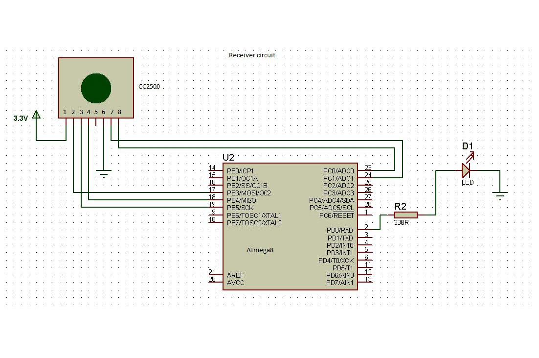
Circuit Diagrams
Filed Under: Electronic Projects

Questions related to this article?
👉Ask and discuss on EDAboard.com and Electro-Tech-Online.com forums.
Tell Us What You Think!!
You must be logged in to post a comment.