The intruder alarm system has two circuits – one is the sensor circuit where LDR is used to detect intruder by detecting shadow. The other is alarm circuit built of 555 timer IC which triggers a buzzer on receiving the appropriate signal. The duration of the alarm depends on the resistor and capacitor used with 555 IC which has been used as one-shot pulse generator in the circuit. The 434 MHz RF module forms a wireless communication bridge between the two circuits.

Fig. 1: Prototype of Transmitter Side of 555 IC based Wireless Intruder Alarm
Components Required
| Sr. No. | Components Required | Quantity |
|---|---|---|
| 1 | RF Tx module (434 MHz) | 1 |
| 2 | RF Rx Module(434MHz) | 1 |
| 3 | HT12E | 1 |
| 4 | HT12D | 1 |
| 5 | LED | 1 |
| 6 | Resistor – 10KΩ (Quarter watt) | 2 |
| 7 | Resistor – 1MΩ (Quarter watt) | 1 |
| 8 | Resistor – 50KΩ (Quarter watt) | 1 |
| 9 | Resistor – 1KΩ (Quarter watt) | 1 |
| 10 | LDR | 1 |
| 11 | Resistor – 100KΩ (Quarter watt) | 1 |
| 12 | Transistor – 2n2222A | 1 |
| 13 | Resistor – 47KΩ (Quarter watt) | 1 |
| 14 | Capacitor – 0.1 µF | 2 |
| 15 | IC NE555 | 1 |
| 16 | Buzzer | 1 |
| 17 | Battery – 9V | |
| 18 | Breadboard | |
| 19 | Connecting wires |

Fig. 2: Block Diagram of 555 IC based Wireless Intruder Alarm
Circuit Connections
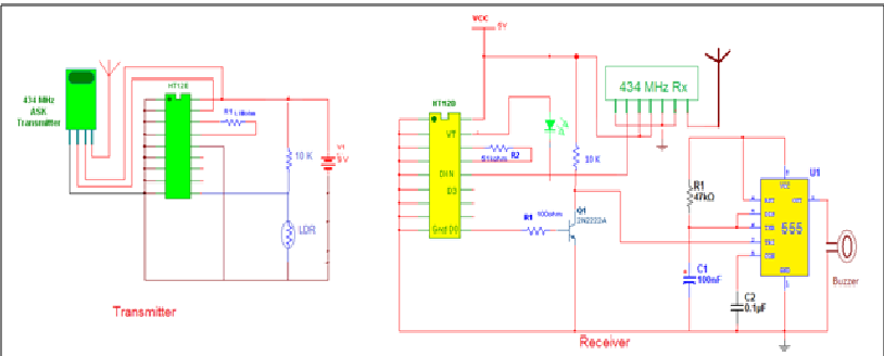
The intruder alarm system has two circuits – the LDR sensor circuit and the 555 based alarm circuit. The sensor circuit is made by using the LDR in pull-up configuration. In this configuration, the LDR is connected between the ground and the output junction. A pull-up resistor of suitable value is connected between the output junction and the VCC. The pull-up resistor used with the LDR is 10K ohm. The output junction is connected to D0 data pin of the HT12E encoder IC. The LDR circuit is interfaced with the RF transmitter having basic setup for circuit connections of HT12E encoder. The address bits of the HT12E are connected to ground to assign an address byte of 0x00 to the transmitter. The pin 14 of the HT12E is hard-wired to ground to enable continuous transmission of the signal. An antenna is attached to pin 4 of the RF transmitter to increase the operational range of the RF module.
In the alarm circuit, an RF receiver section is connected with the 555 based buzzer circuit. The RF receiver has an antenna attached to its pin 8 and serial output from pin 2 is connected to pin 14 of the HT12D decoder IC. The circuit connections of HT12D (and the HT12E) are made as specified by their datasheets. The decoder IC also has all the address bits connected to ground to match the transmitter address 0x00. The respective data bit i.e. the D0 of the 4-bit data signal, is connected to the trigger pin of 555 timer via transistor circuit. The 555 timer is used as one-shot pulse generator in this project. The D0 is connected to base of a 2N2222A transistor through a resistor of 100ohm value. The 2N2222 is an NPN BJT transistor used for low power amplification. It is used in the project to amplify HIGH signal from the D0 data bit. The output from the amplifier transistor is connected to trigger pin of the 555 IC. A combination of 47K ohm resistor and 100nF capacitor is connected at the threshold pin as the required RC combination. A low value capacitor of 0.01uF is connected at control pin of the 555. The buzzer is connected between output pin of 555 IC and the ground so that when the 555 has HIGH output, the buzzer operates.

Fig. 3: Prototype of Receiver Side of 555 IC based Wireless Intruder Alarm
How the Circuit Works
The sensor circuit has an LDR in pull- up configuration. An LDR operates on the basis of light conductivity. Its resistance is higher when no light falls on it but when the light falls on it, its resistance is reduced. This change in resistance occurs due reduction in the resistivity. When light falls i.e. when the photons fall on the device, the electrons in the valence band of the semiconductor material are excited to the conduction band. These photons in the incident light should have energy greater than the band gap of the semiconductor material to make the electrons jump from the valence band to the conduction band. Hence when light having enough energy is incident on the device more & more electrons are excited to the conduction band which results in large number of charge carriers. Thus the resistance is reduced. The LDR can be used in two configurations.
1) Pull-up configuration
2) Pull-down configuration
The pull-up configuration is used in this project. In pull-configuration, the LDR sensor is connected between ground and the output junction and the VCC is provided at the junction via pull up resistor. In such configuration the pull up resistor drops some voltage and rest of the voltage is left to be dropped by the LDR and the output. Hence when there is no light falling on LDR sensor, the LDR has higher resistance and due to parallel connection with load, increased LDR resistance results in lower current draws across it while higher current flows through the load. When light falls on the LDR, its resistance is reduced and current flow through it is increased, resulting into lower current draws at the output. The voltage drop at the output junction remains constant due to parallel connection between LDR and output/load junction and suitable pull-up resistor should be used according to the load connected at it. This configuration is useful when current draw at the output has to be changed by light sensitivity. This configuration allows to receive a HIGH at output when a shadow (i.e. absence of light) falls on the LDR. When a shadow is not falling on LDR, the LDR has full access to illumining lights and it outputs a LOW logic.
So as the shadow falls, a HIGH output is feed to the D0 of the HT12E encoder IC. The same HIGH D0 bit is transmitted over the system and received by the receiver section of RF. The rest of the data bits are not connected and transmits as LOW. Therefore on detecting an intruder 0x1 is transmitted on the RF system.

Fig. 4: Image showing Transmitter and Receiver Sides of 555 IC based Wireless Intruder Alarm
At the alarm system, the same HIGH D0 is reflected at the D0 bit of the HT12D decoder IC on the intruder detection. On receiving HIGH from HT12D’s D0 bit, the HIGH signal is amplified by the 2N2222A transistor. The amplified output is passed to the trigger pin of the 555 IC. The 555 IC operates as pulse generator and outputs a HIGH at the output pin when amplified output is detected at the trigger pin. The duration of the buzzer depends on the RC combination connected at the threshold pin of 555 IC. A combination of 47K ohm resistor and 100nF capacitor is used as the RC combination which allows the buzzer to maintain the sound alert for few seconds.
In this project single alarm circuit has been used. However, multiple alarm circuits can be used with the sensor circuit. The only precaution that has to be taken is that RF receivers in all the alarm circuits should have the same address byte as that of the transmitter section in sensor circuit. The address byte has been maintained 0x00 in this project and can be hard-wired to any byte. An RF module on using with an antenna of standard size and proper transmission power can transmit signals over a distance of 300 metre which is quite enough to encompass any multi-storey building or office building stretched few hundreds of metre.
Circuit Diagrams
Project Video
Filed Under: Electronic Projects
Filed Under: Electronic Projects

Questions related to this article?
👉Ask and discuss on Electro-Tech-Online.com and EDAboard.com forums.
Tell Us What You Think!!
You must be logged in to post a comment.