Engineers Garage

  • Projects and Tutorials
    • Electronic Projects
      • 8051
      • Arduino
      • ARM
      • AVR
      • PIC
      • Raspberry pi
      • STM32
    • Tutorials
    • Circuit Design
    • Project Videos
    • Components
  • Articles
    • Tech Articles
    • Insight
    • Invention Stories
    • How to
    • What Is
  • News
    • Electronic Products News
    • DIY Reviews
    • Guest Post
  • Forums
    • EDABoard.com
    • Electro-Tech-Online
    • EG Forum Archive
  • Digi-Key Store
    • Cables, Wires
    • Connectors, Interconnect
    • Discrete
    • Electromechanical
    • Embedded Computers
    • Enclosures, Hardware, Office
    • Integrated Circuits (ICs)
    • Isolators
    • LED/Optoelectronics
    • Passive
    • Power, Circuit Protection
    • Programmers
    • RF, Wireless
    • Semiconductors
    • Sensors, Transducers
    • Test Products
    • Tools
  • EE Resources
    • DesignFast
    • LEAP Awards
    • Oscilloscope Product Finder
    • White Papers
    • Webinars
  • EE Learning Center
  • Women in Engineering

Wireless Switch Circuit Diagram

By Ashutosh Bhatt

Normally, home appliances are controlled by means of switches, sensors, etc. However, physical contact with switches may be dangerous. The circuit described here requires no physical contact for operating the appliance. You just need to move your hand over the light dependent resistor (LDR). The device connected to it switches “on” when you put your hand over the LDR and remains “on” until you again move your hand over it.

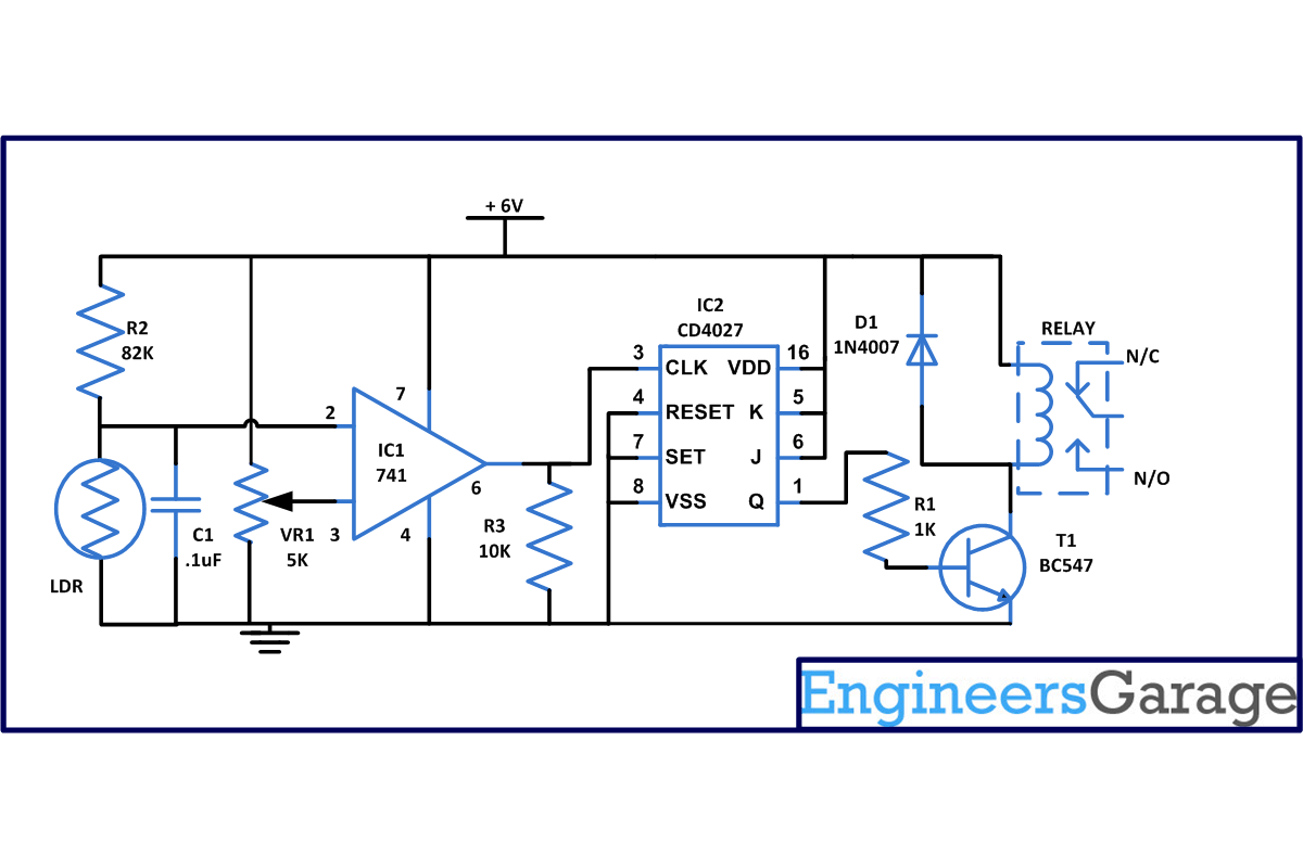
The wireless switch circuit is based on two ICs: one is operational amplifier LM741 and JK Flip Flop CD4027. An op-amp produces an output voltage that is hundreds of thousand times larger than the voltage difference between its input terminals. CD4027 is a master slave JK flip flop IC which works in toggle mode. Here this IC can be used to change the state by the signal applied to one or more control inputs and will have one or two outputs. CD4027 has four inputs namely J, K, Set and Reset and it contain two outputs namely Q and Q bar (Q not).

[[wysiwyg_imageupload:7848:]]

Fig. 1: Prototype Of Wireless Switch Circuit On Breadboard


The wireless switch circuit comprises of Operational amplifier LM741 (used as a sensitive voltage comparator), LDR, Preset VR1 (which provides a reference voltage to the non-inverting terminal pin 3 and LDR), R2( connected to inverting pin 2 of IC1) and few more components.

Working: When we do not put our hand on LDR device remains off and as a result pin 2 of IC1 goes high. Consequently, output pin 6 of IC1 remains low.

As soon as anyone puts his hand over LDR, pin 2 of IC1 goes low in comparison to pin 3 of IC1 . Pin 6 becomes high thus providing a clock pulse to pin 13 of IC2 which is a flip flop whose stage is controlled by the logic levels present at J and K input with some internal control. Change in state occurs at the positive going transition of the clock pulse. In this, set and reset pins are independent of the clock and they are initiated when a high signal is present on any of the input pins.

The circuit shown is triggered on the leading edge of the switch pulse which means that output changes when you again put your hand over LDR. From the circuit you can see that both J and K are tied to high input so at every negative or positive transition, the clock pulse pin 13 toggles between high to low. This can be verified with the help of the truth table of the JK flip flop. Therefore, when it receives the clock pulse from IC1 due to hand over LDR, transistor connected to pin15 starts conducting and we will receive the output with the help of relay. You can adjust the sensitivity of LDR with the help of VR1.

Circuit Diagrams

Circuit-Diagram-For-Wireless-Switch-Circuit

Project Components

  • Capacitor
  • LDR
  • Relay Switch
  • Resistor
  • Transistor BC547

Project Video


Filed Under: 555 Timers, Electronic Projects
Tagged With: 555 timer circuit, cd 4027, ic, lm 741, switch, wireless
 

Questions related to this article?
👉Ask and discuss on EDAboard.com and Electro-Tech-Online.com forums.


Tell Us What You Think!! Cancel reply

You must be logged in to post a comment.

HAVE A QUESTION?

Have a technical question about an article or other engineering questions? Check out our engineering forums EDABoard.com and Electro-Tech-Online.com where you can get those questions asked and answered by your peers!


Featured Tutorials

  • Designing Gate Driver Circuit and Switching Mechanism for Modified Sine Wave Inverter – (Part 9/17)
  • Completing Modified Sine Wave Inverter Design with Full Bridge Circuit and Step Up Transformer – (Part 10/17)
  • Designing an Offline UPS – Part (12 /17)
  • How to reduce Switching Time of a Relay – (Part 15/17)
  • Testing MOSFET – (Part 16/17)
  • Driving High Side MOSFET using Bootstrap Circuitry – (Part 17/17)

Stay Up To Date

Newsletter Signup

Sign up and receive our weekly newsletter for latest Tech articles, Electronics Projects, Tutorial series and other insightful tech content.

EE Training Center Classrooms

EE Classrooms

Recent Articles

  • Renesas to demonstrate first working silicon based on the Arm Cortex-M85 processor
  • STMicroelectronics releases first automotive IMU with embedded machine learning
  • Infineon offers DC-DC controller for full LED headlamps without a microcontroller
  • Vishay launches new high-precision, thin-film wraparound chip resistor
  • STMicroelectronics’ common-mode filters ensure signal integrity in serial interfaces

Most Popular

5G 555 timer circuit 8051 ai Arduino atmega16 automotive avr dc motor display Electronic Part Electronic Parts Fujitsu ic infineontechnologies integratedcircuit Intel IoT ir lcd ldr led maximintegratedproducts microchip microchiptechnology Microchip Technology microcontroller microcontrollers mosfet motor powermanagement Raspberry Pi remote renesaselectronics renesaselectronicscorporation Research samsung semiconductor sensor software STMicroelectronics switch Technology vishayintertechnology wireless

RSS EDABOARD.com Discussions

  • Capacitive Switches
  • CSI-2 FIFO or Line buffer?
  • Temperature sensor readout
  • What is the function of the long stub?
  • Circuit Performance Exploration

RSS Electro-Tech-Online.com Discussions

  • Opamp ciruit
  • Audio equalizer
  • Background of Members Here
  • software PWM
  • SPI Questions
Engineers Garage
  • Analog IC TIps
  • Connector Tips
  • DesignFast
  • EDABoard Forums
  • EE World Online
  • Electro-Tech-Online Forums
  • Microcontroller Tips
  • Power Electronic Tips
  • Sensor Tips
  • Test and Measurement Tips
  • 5G Technology World
  • About Us
  • Contact Us
  • Advertise

Copyright © 2022 WTWH Media LLC. All Rights Reserved. The material on this site may not be reproduced, distributed, transmitted, cached or otherwise used, except with the prior written permission of WTWH Media
Privacy Policy | Advertising | About Us

Search Engineers Garage

  • Projects and Tutorials
    • Electronic Projects
      • 8051
      • Arduino
      • ARM
      • AVR
      • PIC
      • Raspberry pi
      • STM32
    • Tutorials
    • Circuit Design
    • Project Videos
    • Components
  • Articles
    • Tech Articles
    • Insight
    • Invention Stories
    • How to
    • What Is
  • News
    • Electronic Products News
    • DIY Reviews
    • Guest Post
  • Forums
    • EDABoard.com
    • Electro-Tech-Online
    • EG Forum Archive
  • Digi-Key Store
    • Cables, Wires
    • Connectors, Interconnect
    • Discrete
    • Electromechanical
    • Embedded Computers
    • Enclosures, Hardware, Office
    • Integrated Circuits (ICs)
    • Isolators
    • LED/Optoelectronics
    • Passive
    • Power, Circuit Protection
    • Programmers
    • RF, Wireless
    • Semiconductors
    • Sensors, Transducers
    • Test Products
    • Tools
  • EE Resources
    • DesignFast
    • LEAP Awards
    • Oscilloscope Product Finder
    • White Papers
    • Webinars
  • EE Learning Center
  • Women in Engineering