Temperature monitoring and control is one of the most common applications used in the industries. A lot of industrial equipment require constant supervision of temperature like boilers and chemical containers need continuous supervision of equipment or the ambient temperature. Many times, the operating temperature range of the system under supervision is in limits where hardwiring the sensor circuit with the control circuit is not feasible. In such a case, the temperature sensor can be made to transfer temperature readings to the control circuit using wireless mode.
This project is an implementation of wireless temperature reading using the 434 RF module. The module has a range of 50-60 meter and can be extended to 300-350 meter using the antenna with RF module and increasing its transmission power. The project gets the embedded intelligence from Arduino Pro Mini. The temperature sensor used in the project is LM35 which can read temperature between -40° to 150° C.
Components Required
| Sr. No. | Components Required | Quantity |
|---|---|---|
| 1 | RF Rx Module(434Mhz) | 1 |
| 2 | RF Tx Module(434Mhz) | 1 |
| 3 | LM35 Temperature sensor | 1 |
| 4 | LCD | 1 |
| 5 | 1 k Pot | 1 |
| 6 | 10 k resistor | 1 |
| 7 | Arduino pro mini development board | 2 |
| 8 | Battery – 9V | 2 |
| 9 | Breadboard | 2 |
| 10 | Connecting wires | – |
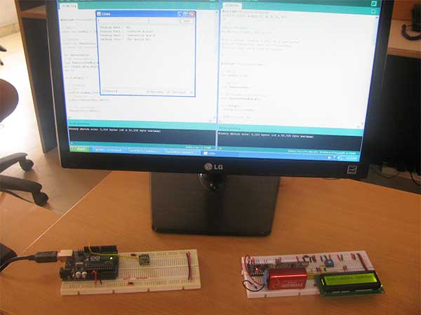
Fig. 1: Prototype of Arduino and Flex Sensor based Servo Motor Angle Controller
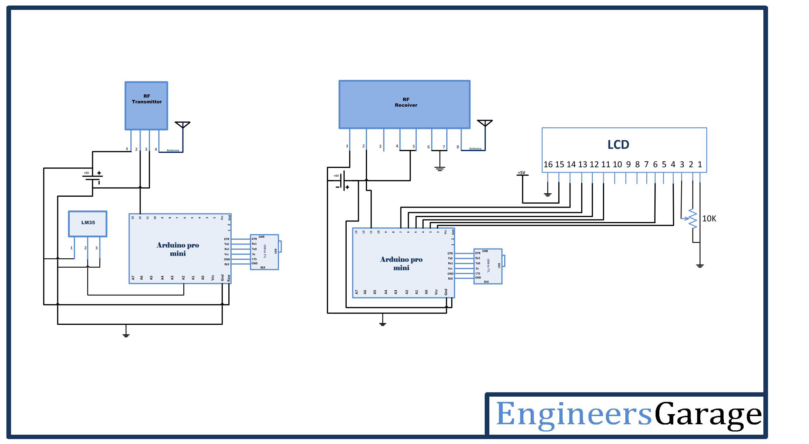
Circuit Connections
The project consists of two circuits – a) temperature sensor circuit and b) temperature display circuit. In the temperature sensor circuit, the LM35 sensor is used. The LM35 has three pins – VCC (Pin 1), Out (Pin 2) and Ground (Pin 3). The VCC and Ground pin are connected to VCC and ground respectively. The LM35 can be supplied a voltage between 4V and 20V, so a 5V supply is used on it same which is powering the Arduino board. The out pin of the LM35 is connected to A2 pin of the Arduino since the output from the LM35 is analog in nature. The RF transmitter is connected to the Arduino with pin 2 of the module connected to pin 12 of the Arduino board while an antenna is connected to pin 4 of the transmitter for range extension.
On the temperature monitoring circuit, an RF receiver is used which has its serial out pin (Pin 2) connected to Pin 11 of the receiver side Arduino board. An LCD is interfaced to the Arduino board for displaying temperature readings.
The 16X2 LCD display is connected to the Arduino board by connecting its data pins to pins 7 to 4 of the Arduino board. The RS and E pins of LCD are connected to pins 3 and 2 of the Arduino Pro Mini respectively. The RW pin of the LCD is grounded.
| LCD | Arduino UNO |
|---|---|
| RS | 3 |
| RW | GRND |
| E | 2 |
| D7,D6,D5,D4 | 7,6,5,4 Respectively |
The standard code library for interfacing Arduino UNO and Arduino Pro Mini are used in the project to program LCD with the board.

Fig. 2: Circuit Diagram of Arduino and Flex Sensor based Servo Motor Angle Controller
How the circuit works
LM35 is an analog temperature sensor. Its circuit is sealed and safe from oxidation. It can measure temperature from -40° to 150° C. The voltage output from the out pin of the sensor is directly proportional to the temperature in degree Celsius. The voltage output increases or decreases by a factor of 0.01 V per degree Celsius rise or fall of temperature. The sensor has an accuracy of +/-0.4°C to +/-0.8°C.
According to the datasheet of LM35 the scale of output voltage variation is given by:
Vout = 10mV/C * Tambient
Therefore, the temperature from the voltage output of the sensor can be deduced using the following formulae -:
Tambient = 0.1* Vout where Vout is measured in millivolts
= 0.1 * Vout * 1000 (Converting Vout from Millivolts to volts)
= 100* Vout *5 (for supply voltage to LM35 being 5V)
= 500*Vout/1024 (as the analog signal is 10-bit long on sampling)
= 0.488 * Vout
The output pin of the temperature sensor is connected to A2 analog pin of the Arduino. The analog voltage is read by the Arduino using standard library functions in the program code. The program code of transmitter side Arduino not only reads the analog reading, it converts the reading to a series of decimal characters and serial them out to the RF transmitter.
Over the transmission of the digitized reading over RF system, the reading characters are detected by the RF receiver and serial out to the receiver side Arduino to its pin 11. The program code of the receiver side Arduino detects the reading’s characters and convert them to integers for passing on to the 16X2 LCD display. The characters are passed to LCD and displayed in a presentable format.

Fig. 3: Prototype of Transmitter Circuit for Wireless Temperature Monitor
Programming Guide
On the transmitter side Arduino, first, the program code imports the required standard libraries. The VirtualWire library is required to read the analog reading from pin A2. Global variables ledPin and Sensor1Pin are declared and mapped to Pin 13 where transmission progress indicator LED is connected and Pin A2 where output pin of LM35 temperature sensor is connected respectively. A character array Sensor1CharMsg is declared to stored decimal representation of the temperature reading.
#include <VirtualWire.h>
A setup() function is called where indicator LED pin is set to output while sensor connected pin is set to input mode using the pinMode() function.
The baud rate of the Arduino is set to 9600 bits per second using the serial.begin() function. The baud rate for serial output is set to 2000 bits per second using the vw_setup() function of the VirtualWire library.
A loop() function is called where the analog reading (in terms of voltage measurement at the pin) is fetched using the analogRead() function and stored in “Sensor1Data” variable. The temperature is deduced by applying the voltage to temperature formulae as stated in the datasheet of LM35. The temperature reading (an integer value) is converted to the character of base 10 using itoa() function and stored in Sensor1CharMsg array.
The temperature reading is serially out as human-readable ASCII text using the Serial.print() and Serial.println() function.
The transmission progress indicator LED is switched on by passing a HIGH to pin 13. The character message containing the temperature reading is sent serially using the vw_send() function and vw_wait_tx() is used to block transmission until a new message is available for transmission. The LED at pin 13 is switched OFF by passing a LOW to indicate successful transmission of the message.
This ends the transmitter side Arduino code.
On the receiver side Arduino, the program code first imports the required standard libraries. LiquidCrystal.h is imported to interface the LCD and VirtualWire library is imported to read serial input from the RF receiver. The pins 2 to 7 are mapped to Liquid Crystal object LCD.
The pin 13 where transmission progress indicator LED is connected is assigned to led pin variable and two variables – “Sensor1Data” to capture analog reading of LM35 in integer form and “Sensor1CharMsg” to store character representation of the reading are declared.
A setup() function is called where baud rate of the Arduino is set to 9600 bits per second using Serial.begin() function. The LCD object is initialized to 16X2 mode and initial messages are flashed to the LCD. The led connected pin and pin connected to RS and RW are set to output mode using the pinMode() function.
The RF transmitter and receiver module does not have Push To Talk pin. They go inactive when no data is present to transmit or receive respectively. Therefore vw_set_ptt_inverted(true) is used to configure push to talk polarity and prompt the receiver to continue receiving data after fetching the first character. The baud rate for serial input is set to 2000 bits per second using vw_setup() function. The reception of the data is initiated using vw_rx_start().
A loop() function is called inside which, array “buf[]” to read serial buffer and “buflen” variable to store buffer length are declared.
The character buffer is detected using the vw_get_message() function, if it is present, a counter “i” is initialized and LED connected to pin 13 is switched on by sending a HIGH at pin 13 to indicate successful detection of the character buffer. The character buffer is stored in the Sensor1CharMsg array using the for loop with the initialized counter.
The null character is detected in the buffer stream so that no garbage value goes to the LCD display. The characters received from the buffer are converted to the integer value and stored in “Sensor1Data” variable.
The variable value along with relevant strings enclosed is passed to the microcontroller’s buffer and passed to the LCD for display in a presentable format.
Project Source Code
###
#include <VirtualWire.h> // LED's const int ledPin = 13; // Sensors const int Sensor1Pin = A2; int Sensor1Data; char Sensor1CharMsg[4]; void setup() { // PinModes // LED pinMode(ledPin,OUTPUT); // Sensor(s) pinMode(Sensor1Pin,INPUT); // for debugging Serial.begin(9600); // VirtualWire setup vw_setup(2000); // Bits per sec } void loop() { // Read and store Sensor 1 data Sensor1Data = analogRead(Sensor1Pin); int temp = Sensor1Data*0.488; // Convert integer data to Char array directly itoa(temp,Sensor1CharMsg,10); // DEBUG Serial.print("Sensor1 Integer: "); Serial.print(temp); Serial.print(" Sensor1CharMsg: "); Serial.print(Sensor1CharMsg); Serial.println(" "); delay(1000); // END DEBUG digitalWrite(13, true); // Turn on a light to show transmitting vw_send((uint8_t *)Sensor1CharMsg, strlen(Sensor1CharMsg)); vw_wait_tx(); // Wait until the whole message is gone digitalWrite(13, false); // Turn off a light after transmission delay(200); } // END void loop... #include <LiquidCrystal.h> #include <VirtualWire.h> LiquidCrystal lcd(2, 3, 4, 5, 6, 7); // LED's int ledPin = 13; // Sensors int Sensor1Data; // RF Transmission container char Sensor1CharMsg[4]; void setup() { Serial.begin(9600); lcd.begin(16, 2); lcd.print("ENGINEERS GARAGE"); lcd.setCursor(0, 1); // sets the digital pin as output pinMode(ledPin, OUTPUT); pinMode(9, OUTPUT); pinMode(8, OUTPUT); // VirtualWire // Initialise the IO and ISR // Required for DR3100 vw_set_ptt_inverted(true); // Bits per sec vw_setup(2000); // Start the receiver PLL running vw_rx_start(); } // END void setup void loop(){ uint8_t buf[VW_MAX_MESSAGE_LEN]; uint8_t buflen = VW_MAX_MESSAGE_LEN; // Non-blocking if (vw_get_message(buf, &buflen)) { int i; // Turn on a light to show received good message digitalWrite(13, true); // Message with a good checksum received, dump it. for (i = 0; i < buflen; i++) { // Fill Sensor1CharMsg Char array with corresponding // chars from buffer. Sensor1CharMsg[i] = char(buf[i]); } // Null terminate the char array // This needs to be done otherwise problems will occur // when the incoming messages has less digits than the // one before. Sensor1CharMsg[buflen] = '�'; // Convert Sensor1CharMsg Char array to integer Sensor1Data = atoi(Sensor1CharMsg); // DEBUG Serial.print("Sensor 1: "); Serial.println(Sensor1Data); lcd.setCursor(0, 2); lcd.print("Temperature ="); lcd.print(Sensor1Data); // change the analog out value: if(Sensor1Data > 50){ digitalWrite(9,HIGH); delay(2000); } digitalWrite(9,LOW); } }
###
Circuit Diagrams
Project Video
Filed Under: Electronic Projects
Filed Under: Electronic Projects

Questions related to this article?
👉Ask and discuss on Electro-Tech-Online.com and EDAboard.com forums.
Tell Us What You Think!!
You must be logged in to post a comment.