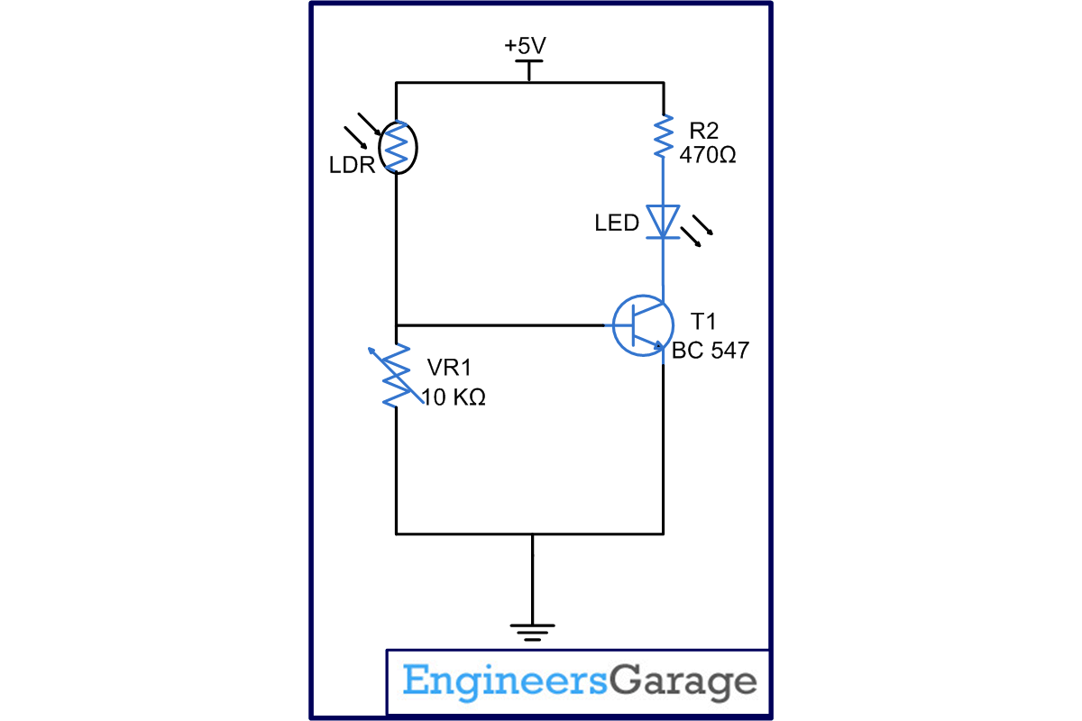
This circuit based project explains the principle of operation of LDR (light dependence resistor). The circuit has various applications like shadow alarm, automatic night/morning lamp.
As the name suggests, LDR is a type of resistor whose working depends upon only on the light falling on it. The resistor behaves as per amount of light and its output directly varies with it. In general, LDR resistance is minimum (ideally zero) when it receives maximum amount of light and goes to maximum (ideally infinite) when there is no light falling on it.
A critical factor that decides LDR’s working is the frequency of light which should cross a threshold value so as to make LDR respond. Keep on reading to find out how the circuit is designed and how it is made to work.
LDR, an acronym for light dependent resistor is a resistor whose resistance is dependent on light. In this project, resistance of LDR is of the order of Mega Ohms in the absence of light and reduces to a few ohms in presence of light. In this circuit when the light falls on LDR, the resistance of LDR becomes low and the entire voltage drop takes place across the variable resistance VR1 (10K). As a result the base of transistor (T1) gets high input and it gets biased thereby glowing the LED. When no light falls on LDR, the resistance of LDR becomes high so almost entire voltage drop takes place across it and the base of transistor is at low potential. So transistor does not gets biased nor it becomes conducting, hence switching off the LED. The sensitivity of the circuit can be adjusted by varying the preset VR1.
Circuit Diagrams
Project Components
Filed Under: Electronic Projects


Questions related to this article?
👉Ask and discuss on EDAboard.com and Electro-Tech-Online.com forums.
Tell Us What You Think!!
You must be logged in to post a comment.