Working of OR Gate Using Diode
Till now we have talked about the basics of logic gates and their use in Electronics. For details, please read our article on Logic Gates. Here, we will learn about one of the three major Gates i.e. OR gate.
In mathematical terms, OR gate works on addition operation and may have two or more inputs but it produces only one output. An OR gate produces an output of logic 0 or LOW only when all the input values are at logic 0 or at LOW state. Other than this, it always produces an output of logic 1. The operational symbol of OR gate is ‘+’ and the expression for OR gate is Z (output) = x+y+ … (Inputs).

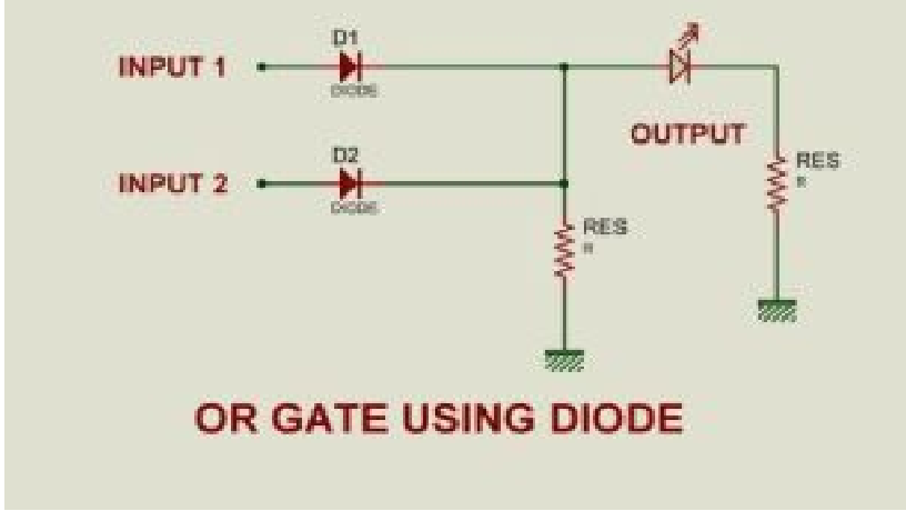
Fig. 1: Circuit Diagram of Diode based OR Gate
OR gate can be realized by Diode Resistance Logic (DRL) or by Transistor-Transistor Logic (TTL). Presently, we will learn how to implement the OR gate using DRL (Diode Resistance Logic). To realise OR gate, we will use a diode at every input of the OR gate. The anode part of diode is connected with input while the cathode part is joined together and a resistor, connected with the cathode is grounded. In our case, we have taken two inputs which can be seen in the circuit above.
When both the inputs are at LOW or logic 0 or 0V state then the diodes D1 and D2 become reverse biased. Since the anode terminal of diode is at lower voltage level than the cathode terminal so diode will act as open circuit so there is no voltage across resistor and hence output voltage is same as ground. When either of the diodes is at logic 1 or HIGH state then the diode corresponding to that input is forward bias. Since this time anode is at high voltage than cathode therefore current will flow through forward biased diode and this current then appears on resistor causing high voltage at output terminal also. Hence at output we get HIGH or logic 1 or +5V. So, if any or both inputs are HIGH, the output will be HIGH or “1”. The Truth table for OR gate can be seen below:
| INPUT | OUTPUT | |
|---|---|---|
| X | Y | Z |
| 0 | 0 | 0 |
| 0 | 0 | 1 |
| 1 | 0 | 1 |
| 1 | 1 | 1 |
Filed Under: Tutorials


Questions related to this article?
👉Ask and discuss on EDAboard.com and Electro-Tech-Online.com forums.
Tell Us What You Think!!
You must be logged in to post a comment.