1. Oscilloscope – An introduction
The oscilloscope is basically a graph-displaying device – it draws a graph of an electrical signal. It is mostly used to display time varying signals: the vertical (Y) axis represents voltage, the horizontal (X) axis represents time. The intensity or brightness of the display is often referred to as Z axis.
2. When to use an Oscilloscope
If you want to measure voltage output of a device/circuit, you can very well do that with the multimeter. For measurement of frequency, frequency counters are available. This function is available in high end multimeters also. So, the question is “When should I use an oscilloscope?” or “Do I need an Oscilloscope at all?”.
Though low cost, easy to use multimeters can give you the measurement of voltage or frequency, they can’t give you the exact profile of the signal. Multimeters report only the RMS voltage. Frequency detection is limited to single tone signal. Oscilloscope provides complete voltage profile with timing information. It displays the signal and allows measurement of peak-to-peak voltage, mean voltage, rms voltage, frequency, time period, rise time, fall time, etc.
3. Types of Oscilloscope
Analog:
Analog Oscilloscope are not available commercially nowadays. They used CRT and used to plot continuously varying voltages directly on the display.
Digital
Digital Oscilloscope uses an ADC to convert measured voltage into digital information. It uses the acquired samples to display the waveform on the display.
They are further classified in following categories – Digital Storage Oscilloscope(DSO), Digital Phosphor Oscilloscope(DPO), Mixed Signal Oscilloscope(MSO), Digital Sampling oscilloscopes
But, as a user, type of oscilloscope doesn’t make any difference. The oscilloscopes are different in their architectures, features, etc. From the user point of view, he has to deal with almost similar controls, with some differences in their physical appearances.
4. FAMILIASRIZATION WITH OSCILLOSCOPES
The basic controls on an oscilloscope are there to provide following functions
The front panel of an oscilloscope normally has control sections divided into Vertical, Horizontal, and Trigger sections. Vertical Controls provide functions of Voltage Scaling & Voltage Shifting. Horizontal Controls provide functions of Time Scaling & Time Shifting. There are also display controls and input connectors.
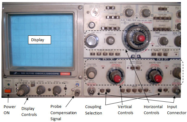
2 Channel Analog Oscilloscope (Important Controls indicated)
5. GETTING STARTED
a) Grounding
Grounding is very important aspect which is usually ignored. Grounding the Oscilloscope protects you from a hazardous shock. Grounding yourself also protects the circuits from damage.
Ensure that the power point has a proper earth ground. Wear a grounding wrist strap to ground yourself. The strap grounds all the static charges to earth ground
b) Switching ON your scope.
First thing you have to do is to connect 230VAC mains to the oscilloscope using power chord. After providing power to the oscilloscope, switch ON the Power ON button.
c) Probe identification
Next thing is to check the probe we want to use for the measurements. It is important to use the proper probe. A probe is not a simple coaxial cable with a connector; it actually is specially designed so that it doesn’t pick up stray signals. Probes should not influence the behaviour of the circuit being tested. Interaction of the probe and oscilloscope with the circuit being tested is called circuit loading.
a. Probes are of two types: Active and Passive.
Passive Probes:
10X attenuator probes should be used preferably to minimise circuit loading. For frequencies higher than 5KHz, circuit loading is significant and hence 10X probe should be used.
For the probes where X is used as suffix, the number signifies the attenuation factor, e.g., 10X, 100X, etc. When X is used as a prefix, the number signifies magnification factor, e.g., X10, X100.
Another fact to be considered is that the 10X probes reduce the amplitude of the signal on the screen. Hence, for smaller(~10 mV) signals, 1X probe is used.
Active Probes
Such probes need power for their operation and performs functions like amplification, etc.
For general applications, passive probes(10X) are commonly used.
d) Probe Compensation
Probe compensation means balancing the electrical properties of the probe with the oscilloscope for accurate measurements. Before making any measurements, probe compensation should be done.
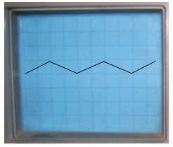
For compensating a probe, a square wave signal is made available at a terminal on the front panel of the oscilloscope. After connecting the probe to the BNC input connector, connect the ground clip of the probe to the ground terminal and connect the probe tip to the probe compensating signal terminal. A square signal appears on the oscilloscope screen.
If signal appearing on the oscilloscope is not a perfect square wave, the probe is either undercompensated or overcompensated. In that case, probe must be adjusted using ‘Compensating Screw terminal’ available on the probe.
e) Coupling
Coupling means the method used to connect an electrical signal from one circuit to another. Three different types of couplings are provided in the oscilloscopes: AC, DC and Ground.
Ground Setting disconnects the input signal from the vertical system. It helps to determine the location of zero volts on the screen.
AC Coupling will block the DC content of the signal. It is useful when AC+DC amplitude is too large for the volt/div setting.
DC Coupling will display full AC+DC content of the signal.
While making measurements on a AC signal with DC bias, AC coupling is preferred. For DC signal measurement, only DC coupling should be used.
For AC signals with no DC content, AC or DC coupling can be used.
f) Termination
For input signal terminations, 50? and 1M? options are there. Depending upon the input cable/probe, select appropriate termination.
[header = Understanding Measurements]
Understanding Measurements:
Any periodic signal has an amplitude, frequency and phase.


Therefore, when a signal is displayed on an oscilloscope, its amplitude, frequency and phase can be measured.
For Non periodic signals, frequency (and phase) is changing constantly. For DC signals also, only amplitude is measured.
MAKING BASIC MEASUREMENT:
a) Connect the signal to be measured to the oscilloscope input(BNC) connectors
b) The signal will appear on the display.

c) The signal can be made to occupy desired number on divisions on the vertical scale of the display using Volts/Division control. Volts/ division setting varies the size of the waveform on the screen.
1 Vp-p will occupy one division on the screen with 1V/div. setting. Same signal will occupy 2 divisions with 500 mV/div.

d) X-axis can also be made to accommodate different number of cycles of the signal.
With 0.5 sec/div, 1 Hz signal will have 5 cycles on the screen whereas with 0.25 sec/div, 2.5 cycles of the same signal will appear on the screen.
e) Using VERTICAL position control, waveform can be made to move up or down the screen.

f) Once a waveform appears on the screen, measurements can be made as mentioned in the previous section.

Volt/div Setting = 1 V/div
Time/div Setting = 0.25 sec/ div.
No of occupied vertical divisions = 4
No of horizontal divisions occupied in one cycle = 4
Therefore,
Peak-to-Peak Amplitude : 4 div X 1V/div = 4 V
Period = 0.25 sec/div X 4 div. = 1 sec
Frequency = 1 Hz.
Modern oscilloscope don’t require you to do all such calculations. All measurements – amplitude (peak-to-peak, rms, mean, etc.), time(period, frequency, etc) are available on-screen on a mouse click.
Shown below is the Tektronics DPO. It has a Windows based GUI software.

In addition, there is an Autoset Button. Pressing that button automatically adjusts the vertical and horizontal settings for proper display of the input signal.
Digital Oscilloscopes have various other features and functions and the tutorial covering all details will be covered later.
Filed Under: Electronic Projects

Questions related to this article?
👉Ask and discuss on EDAboard.com and Electro-Tech-Online.com forums.
Tell Us What You Think!!
You must be logged in to post a comment.