INTRODUCTION:
This project demonstrates the use of xbee as the transceiver where the robot is controlled and distance is measured wirelessly through the xbee. The robot can be moved to the place within the range OF 30m (indoor) or 100m (outdoor) to measure the any distance. The person only just need to operate the robot using the movement joystick in the receiver side, where person no need to move from the place to measure the distance with his tape.

XBee Wireless Joystick control And Distance Measuring Robot
@page { margin: 2cm }
p { margin-bottom: 0.25cm; direction: ltr; line-height: 120%; text-align: left; orphans: 2; widows: 2 }
a:link { color: #0000ff }
COMPONENTS REQUIRED:

BLOCK DIAGRAM:
TRANSCEIVER (CONTROLLING SIDE):

XBee Wireless Joystick control And Distance Measuring Robot Block Diagram
TRANSCEIVER (ROBOT SIDE):

XBee Wireless Joystick control And Distance Measuring Robot Block Diagram
PROJECT DESCRIPTION:
Xbee – wireless joystick control and distance measuring robot consist of 2 arduino microcontroller in which one setup is interfaced with the joystick for controlling the direction of the robot and LCD to display the direction and distance measured by robot and interfaced with xbee for wireless transmission and reception. Another setup is mounted on the robot which consists of arduino controller interfaced with xbee for receiving the data, for the movement of the robot with two DC motors with the wheels attached to it are fixed with chassis. As the motor cannot be directly controlled by the microcontroller, the H-bridge L293D motor driver IC is used to control the motor, Ultra sonic sensor is used to measure the distance between the things that user want. The required power to microcontroller, sensors and motor driver are provided with the help of 12v battery connected to 12v and 5v voltage regulator. The complete circuit diagram, connections and working are explained below.
CIRCUIT CONNECTIONS:
Two Arduino uno are used in this project, where both are connected with xbee radios for transceiver operation.
TRANSCEIVER (CONTROLLING SIDE):
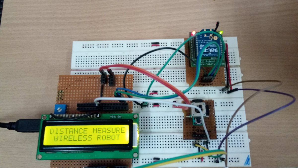
XBee Wireless Joystick control And Distance Measuring Robot
ARDUINO UNO:
The Arduino uno is ATmega328 based microcontroller board. The board comes with built-in arduino bootloader. It has 14 digital input/output pins (of which 6 can be used as PWM outputs), 6 analog inputs, an on-board resonator, a reset button, and holes for mounting pin headers. While programming the board can be connected to the PC using USB port and the board can runs on USB power, to know more Arduino Uno.
POWER SUPPLY:
In the circuit, Arduino board, joystick module, LCD and xbee module need a 5V regulated DC supply for operation. The supply to the arduino board is powered with 5v by USB cable. The voltage input for xbee, LCD and joystick is drawn from 5V Vout pin of arduino.
JOYSTICK:
In this project, we will be using joystick module to control the movement of robot by moving the joystick to the particular direction. The two output data signals of joystick module are analog in nature and it cannot be processed directly by Arduino microcontroller. For this, we will use the ADC of the Arduino microcontroller to convert the analog signals to digital values. So, it’s connected to the Analog input port, where X-out to A0 and y – out to A1. After converting the analog signals of joystick to digital values, the Arduino microcontroller will process the digital values to find different joystick movement.
XBEE S1 MODULE:
Zigbee is a wireless communication module which use IEEE 802.15.4 standard. 802.15.4 is a IEEE standard for low power applications of radio frequency. It used in many products for wireless communication functionality. It can be used as a transmitter and receiver both. It uses serial communication to send and receive data. It has two series, series 1 and series 2. Series 1 is comparatively easy to use and it is recommended for beginners. Here in this project we use series 1 xbee. Series 1 zigbee module cannot work in mesh network. Mean it cannot talk to more than one zigbees. Here It forms simple serial communication where TX of xbee is connected with RX of arduino and RX of xbee to TX of arduino. In this part Xbee acts as a transmitter part. To learn more click here Zigbee.
LCD MODULE:
The 16X2 LCD display will be used to display the distance measured and direction of robot. It is connected to the Arduino board by connecting its data pins to pins 3 to 6 of the Arduino board. The RS and E pins of the LCD are connected to pins 13 and 12 of the Arduino UNO respectively. The RW pin of the LCD is grounded.
@page { margin: 2cm }
p { margin-bottom: 0.25cm; direction: ltr; line-height: 120%; text-align: left; orphans: 2; widows: 2 }
a:link { color: #0000ff }

The standard open-source library for interfacing LCD with Arduino UNO is used in the project. The library works as expected and needs no changes or modifications.
TRANSCEIVER (ROBOT SIDE):
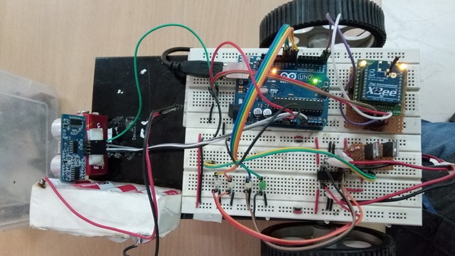
XBee Wireless Joystick control And Distance Measuring Robot
ARDUINO UNO:
The Arduino uno is ATmega328 based microcontroller board. The board comes with built-in arduino bootloader. It has 14 digital input/output pins (of which 6 can be used as PWM outputs), 6 analog inputs, an on-board resonator, a reset button, and holes for mounting pin headers. While programming the board can be connected to the PC using USB port and the board can runs on USB power, to know more Arduino Uno.
POWER SUPPLY:
In the circuit, Arduino board, Motor Driver IC supply, ultrasonic sensor and the Xbee module need a 5V regulated DC while DC motor needs 12V regulated DC for its operation. The 12V NIMH battery is used as major power supply. The output from battery is regulated to 5V and 12V using 7805 and 7812 ICs. The pin 1 of both the voltage regulator ICs is connected to the anode of the battery and pin 2 of both ICs is connected to ground. The respective voltage outputs are drawn from pin 3 of the respective voltage regulator ICs. A LED along with a 1KΩ pull-up resistor is also connected between common ground and output pin to get a visual hint of supply continuity.
ULTRASONIC SENSOR:
The HC-SR04 ultrasonic sensor uses sonar to determine distance to an object like bats or dolphins do. It offers excellent non-contact range detection with high accuracy and stable readings. From 2 cm to 400 cm. It operation is not affected by sunlight or black material like Sharp rangefinders. In this project setup the ultrasonic sensors are used, to detect the obstacle in which trigger pin of sensor is connected to A0 pin of arduino and echo pin to A1 pin of arduino.
L293D MOTOR DRIVER:
L293D is a dual H-bridge motor driver integrated circuit (IC). Motor drivers act as current amplifiers since they take a low-current control signal and provide a higher-current signal. This higher current signal is used to drive the motors. For to know about IC function, pin description and datasheet refer L293D. In this project the arduino digital pin 2 and 3 is connected to the Input A 2nd and 7th pin of L293 D respectively and the arduino digital pin 4 an 5 is connected to the input B 10th and 15th of L293 D IC respectively. Enable pin of L293D is supplied with 5V and the 4, 5, 12, 13 pins are connected to ground. 8th pin of L293D IC is supplied with 12V for motor power.
GEARED DC MOTOR:
The 12V DC Geared Motor can be used in variety of robotics applications and is available with wide range of RPM and Torque, which allow your robot to move based on the control signal it receives from the motor driver IC. Two geared DC motors are used to run the robot. Left motor positive and negative is connected to output A side pin 3rd and 6th of L293D IC and right motor positive and negative is connected to output B pin 11th and 14th of L293D IC respectively.
XBEE S1 MODULE:
In this part Xbee is used as transceiver which is mounted on the robot, it follows the serial communication with the arduino. TX of xbee is connected with RX of arduino and RX of xbee to TX of arduino.
WORKING DESCRIPTION:
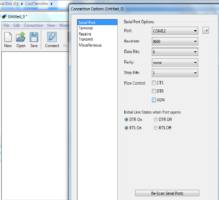
CONFIGURING XBEE MODULES:
The coolterm terminal software is used to configure xbee. In order to make pc to communicate directly with the xbee, even arduino board can be used by removing the controller IC or you can just upload empty simple sketch to the arduino boards, which makes xbee to directly communicate with computer not to arduino. Where connection between arduino and xbee should be like TX of xbee to TX of arduino and RX of Xbee to RX of arduino.
After that open up the coolterm application and choose connection -> options -> serial port select the comport and set the baud rate and go to Terminal option select the Local echo check box to display what you type and click OK to save changes.

To configure xbee the following AT commands should be used, at first make the xbee to enter into a command mode by entering +++ in the terminal once it gets OK then follow with the AT commands.
First off, XBEE radios only operate at a given baud rate, this is the number of bits per second that the XBEE can send. A brand new xbee will default to 9600bps, which is pretty slow. We can change the baud rate, by changing the ATBD register. Both of our XBEEs have to be the same baud rate to talk to one another. The available baud rates (and corresponding ATBD value) are:
1 = 2400bps
2 = 4800bps
3 = 9600bps
4 = 19200bps
5 = 38400bps
6 = 57600 bps
7 = 115200 bps
Here we have set with baud rate 9600, so in order to set that baud rate the command should be used as
ATBD3
The next parameter of interest is the Personal Area Network ID. This is a number shared amongst each XBEE in a network. For now, we are only using 2 XBEEs, but we could have many, many more in a single network. XBEEs on different networks do not “see” each other. The default PAN is 3332, so you should avoid that number. The PAN ID is stored in ATID.
We have set with the following ID
ATID1001
Once both of our XBEEs are on the same network, we can give each one an address number, denoted by ATMY. We can also set the destination address, which is what address number to talk to, denoted ATDL (for destination low, we really don’t need to use the high bytes if we keep our address numbers < 16 bits in length). A sample setup of two XBEEs that will talk directly to one another, at 38.4kbps: Use the following command
ATMY10
ATDL11
The both xbees will be configured as
XBEE1:
ATID1001
ATMY10
ATDL11
ATBD3
XBEE2:
ATID1001
ATMY11
ATDL10
ATBD3
We can also easily set parameters. An important thing to note though is that changes we make are stored in temporary memory, if we power the XBEE device off, they are lost. We need to send ATWR to write the changes to non-volatile memory.

PROJECT DESCRIPTION:

XBee Wireless Joystick control And Distance Measuring Robot
Make the circuit connections according to the circuit diagram and the description given. At first both the transmitter and the Receiver circuit setup are powered up. The LCD shows the Initial message and starts displaying the direction of the robot. The robot starts moving in direction with respect to the readings from the joystick module. The movement of joystick handle can control the movements of the robot as forward, backward, left and right. The according to values read by arduino the data’s are transmitted wirelessly through the xbee, where the data are received by xbee mounted on robot and the data is given to microcontroller to process and control the direction of robot by giving input to motor driver L293D IC from digital pins of microcontroller by making the pin high. As our main purpose is to measure the distance, so the robot is moved to particular place and stopped and as joystick switch is pressed the control signal sent instructs to measure the distance, The Ultrasonic Sensor sends out a high-frequency sound pulse and then times how long it takes for the echo of the sound to reflect back. The sensor has 2 openings on its front. One opening transmits ultrasonic waves, (like a tiny speaker), the other receives them, (like a tiny microphone).
The speed of sound is approximately 341 meters (1100 feet) per second in air. The ultrasonic sensor uses this information along with the time difference between sending and receiving the sound pulse to determine the distance to an object. It uses the following mathematical equation:
Distance = Time x Speed of Sound divided by 2
The measured distance transmitted to the user side and the distance measured is displayed on the LCD.
PROGRAMMING DESCRIPTION:
Transceiver Program (Controlling side):
The Arduino code loads the LiquidCrystal.h to handle LCD display. The arduino pins are initialized for connecting the joystick module.

In the setup() function the pinMode for joystick is declared and the baud rate for serial communication with the xbee module is set to 9600 bits per second using begin() method on Serial class.
The loop() function is called in which the voltage level from the joystick is read and stored in variables declared for it. With the voltage value compared with the reference value, by following the condition respective data is sent to the xbee using pritln() function.

In the loop() function, on pressing the joystick switch it looks for the distance measurement and the distance are received from xbee, as the data received is a byte it is converted to integer using atoi function and stored in the buffer.

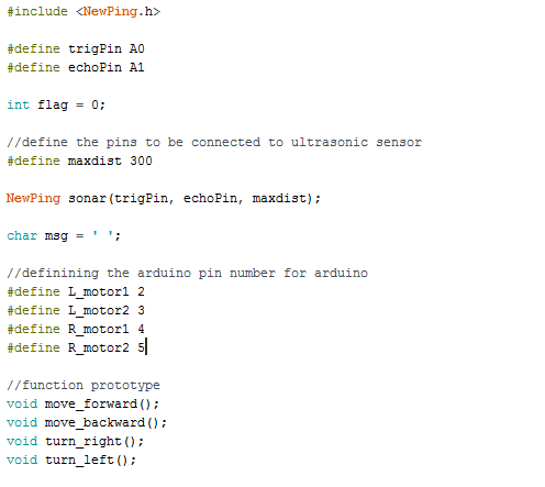
Transceiver program (Robot Side):
The Arduino code loads the Newping.h library to handle ultrasonic sensor, the character variable is initialized to store the receiving data. Motor pins are defined which is connected with the arduino to motor driver IC and trigger and echo pin of ultrasonic sensor is also defined. In the setup() function begin() is initialized with 9600 baud rate to receive the serial data from xbee. Motor pin modes are defined as output pin.

The loop() function is called in which it continuously checks for the incoming serial data, if serial data is available, the data is read using serial.read() function and stored in the variable. Then stored data is checked with the condition mentioned. Then with respect to conditions function call for robot movement is carried out.
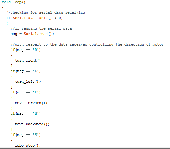
When the command is received to measure the distance, the readsensor() function is called which measures the distance between the object using inbuilt sonar.ping() function.

Project Source Code
Project Source Code
### //Program to#include <LiquidCrystal.h> LiquidCrystal lcd(13, 12, 6, 5, 4, 3); // Arduino pin numbers const int SW_pin = 8; // digital pin connected to switch output const int X_pin = 1; // analog pin connected to X output const int Y_pin = 0; // analog pin connected to Y output int x_value = 0; int y_value = 0; int sw_value; void setup() { Serial.begin(9600); pinMode(SW_pin, INPUT); lcd.begin(16, 2); digitalWrite(SW_pin, HIGH); lcd.setCursor(0,0); lcd.print("Engineers Garage"); lcd.setCursor(0,1); lcd.print(" "); delay(3000); lcd.setCursor(0,0); lcd.print("DISTANCE MEASUREING"); lcd.setCursor(0,1); lcd.print(" WIRELESS ROBOT"); delay(3000); lcd.setCursor(0,1); lcd.print(" "); } void loop() { sw_value = digitalRead(SW_pin); x_value = analogRead(X_pin); y_value = analogRead(Y_pin); if(x_value > 900) { Serial.println("F"); lcd.setCursor(0,0); lcd.print("ROBOT MOVEMENT "); lcd.setCursor(0,1); lcd.print(" FORWARD"); } else if(x_value < 90) { Serial.println("B"); lcd.setCursor(0,0); lcd.print("ROBOT MOVEMENT "); lcd.setCursor(0,1); lcd.print(" BACKWARD"); } else if(y_value > 900) { Serial.println("R"); lcd.setCursor(0,0); lcd.print("ROBOT MOVEMENT "); lcd.setCursor(0,1); lcd.print(" RIGHT"); } else if(y_value < 80) { Serial.println("L"); lcd.setCursor(0,0); lcd.print("ROBOT MOVEMENT "); lcd.setCursor(0,1); lcd.print(" LEFT"); } else if(sw_value == 0) { //Sending the data M to enable measuring Serial.println("M"); //Buffer space for incoming serial data char buffer[] = {' ',' ',' ',' ',' '}; while (!Serial.available()); //when serial is available read the data till newline and store to buffer Serial.readBytesUntil('n', buffer, 7); //converting the charcter to integer int incomingValue = atoi(buffer); Serial.println(incomingValue); //commands for clearing lcd, setting the lcd cursor and to display the distance lcd.clear(); lcd.setCursor(0, 0); lcd.print("Dist. Measured"); lcd.setCursor(0, 1); lcd.print(incomingValue); delay(1000); } else { Serial.println("S"); lcd.setCursor(0,0); lcd.print("ROBOT MOVEMENT "); lcd.setCursor(0,1); lcd.print(" STOP"); } }
###
Circuit Diagrams
| XBee_Wireless_Joystick_control_And_Distance_Measuring_Robot_Circuit_Diagram-4 |  |
| XBee_Wireless_Joystick_control_And_Distance_Measuring_Robot_Circuit_Diagram-3 | 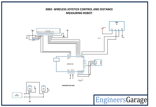 |
Project VideoXBEE - WIRELESS JOYSTICK CONTROL AND DISTANCE MEASURING ROBOT
Filed Under: Electronic Projects
XBEE - WIRELESS JOYSTICK CONTROL AND DISTANCE MEASURING ROBOT
Filed Under: Electronic Projects

Questions related to this article?
👉Ask and discuss on EDAboard.com and Electro-Tech-Online.com forums.
Tell Us What You Think!!
You must be logged in to post a comment.