8051 has established itself as a one of first steps towards microcontroller based learning. With immense potential into several applications and several educational and applicative dimensions, 8051 is a must for every electronic or robotic enthusiast.
The blog electronicswork.wordpress.com/ gives a numerous projects about 8051 microcontroller such as LED interfacing, up counter, stepper motor rotation etc. The projects have been well detailed in terms of explanation, circuit diagram and coding, thus making anyone understand it in simple steps.
In addition to 8051, the blog has also featured VHDL in their latest post. This latest post is suitable for beginners as it gives an introduction to VHDL and teaches on how can make one VHDL code.
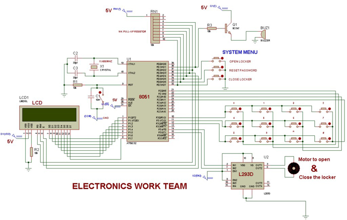
A circuit of one of several projects on 8051
This blog has a well-developed section for regular visitors as one can go through their archives, follow them on several social networks as well as get regular updates through email.
Filed Under: Reviews

Questions related to this article?
👉Ask and discuss on EDAboard.com and Electro-Tech-Online.com forums.
Tell Us What You Think!!
You must be logged in to post a comment.