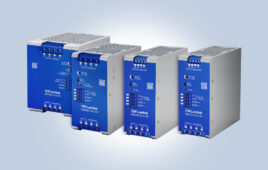
TDK Corporation announces the addition of higher power, three-phase AC input models to the TDK-Lambda DRB series of DIN rail mount power supplies. With 24V, 48V, and 72V outputs, the products are rated for continuous operation at 480W or 960W and can deliver a boost of 720W and 1440W respectively for up to seven seconds.…
TDK introduces series of industrial ac-dc power suppliers
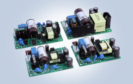
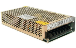
TDK Corporation announces the introduction of the ZWS-C series of 10, 15, 30, and 50W-rated industrial AC-DC power supplies. The products meet EN55011/EN55032-B conducted and radiated EMI in either a Class I or Class II (double insulated) construction, without the need for external filtering or shielding. With electrolytic capacitor lifetimes of up to 15 years,…
Tagore and Inventchip unveil high-efficiency GaN power supply reference design for diverse applications.
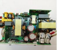
Tagore Technology announced a partnership with Inventchip to introduce a new compact 500 W power supply reference design solution with a Totem Pole PFC front-end and an LLC back-end. Tagore Technology has been delivering disruptive GaN semiconductor solutions for more than 12 years. The reference design uses Tagore’s TP44100SG (90mOhm) and Inventchip’s CCM Totem Pole…
How to design an ac-dc buck converter
An ac-dc converter is commonly used in many devices. Also called a rectifier, it converts alternating current (AC) to direct current (DC). Most electronic devices, such as computers, smartphones, and electronic circuits, operate on DC power. However, there are different ways to convert AC into DC power (as discussed in the previous AC-to-DC conversion article). For…
Minimizing electromagnetic interference in smart motor control for automobiles
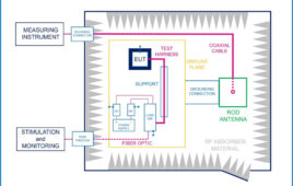
by Sebastiano Grasso, Leonardo Agatino Miccoli, Giusy Gambino, Filippo Scrimizzi, STMicroelectronics, Catania, Italy The automotive landscape constantly evolves, driven by the increasing demand for automation, safety enhancements, and power efficiency. Within this dynamic environment, the deployment of DC motors in automotive body applications has gained significant prominence. These versatile motors find application in both traditional combustion…
What is ac-dc conversion and its various topologies?
This tutorial explains the process of ac to dc conversion and why it is needed. The electricity that is delivered to our home is mainly AC (Alternative Current). Different countries have different standards for domestic AC lines ranging from 100 V to 220 V. Even so, most home appliances are DC (Direct Current)-operated, although devices…
A guide to bipolar junction transistors

The term transistor is derived from the words “transfer and “resistor.” The first semiconductor transistor was invented to replace the triode as an amplifier device, a vacuum tube with three electrodes. The transistor was smaller, lighter, and cheaper than a vacuum tube triode. It also proved easy to construct and had no heat losses like…
How to design a constant current source using a linear buck converter
In many applications, there’s a need for a constant voltage source. However, there are more constant current source applications than constant voltage sources. Most power supplies are voltage sources, including batteries and bench power. A constant current source can be used anywhere a fixed current is required. A resistor can also be used, but the…
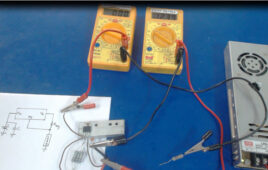
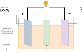
Li-Ion to 12 V DC converter
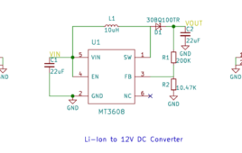
In this era of battery-operated devices, a DC-DC converter is needed to meet the divergent power requirements of the electronic circuitry. A battery is a type of DC Supply whose output voltage varies with its use. This means it cannot maintain a constant voltage at the output due to its discharging characteristics. For this reason,…
Power Failure Indicator in NRF24LE1 (Part 4/14)

Nowadays most of our devices are portable and run on batteries. We often do not know when the battery is about to get discharged. Many systems have the battery voltage display to indicate the battery voltage but what if we don’t have the display in our system. In such a case, using a small LED to indicate low battery is very helpful for users to know about the battery status.
How rechargeable batteries, charging, and discharging cycles work
The battery stores electrical energy in form of chemical energy and the chemical energy again able to convert into electrical energy. The conversion of chemical energy to electrical energy is called discharging. The chemical reaction during discharge makes electrons flow through the external load connected at the terminals which causes the current flow in the…
How do dc-dc converters work?
A DC power supply is used in almost all of devices where a regulated voltage is required. A DC converter implements the process of DC conversion. There are two types of DC converters: Buck converter- Steps down the input source voltage Boost converter – Steps up the input source voltage Conversion topology Linear regulator –…
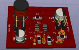
Designing a Switched Mode Power Supply (SMPS)
Everyone must be familiar with the term – Switched Mode Power Supply or SMPS. Yes, they are used in every personal computer. In fact, the Switched Mode Power Supply is widely used with many other devices. Once it is understood that what SMPS actually is, its countless applications can be easily imagined.
How to optimize Arduino for low power design

Power consumption of the embedded controller is a primary concern in low power design. Arduino boards are often used in devices that rely on battery or solar charging. Such devices often deploy far from the power line to have periodic battery replacement or are mobile devices designed for periodic charging cycles. In such a case,…
How to achieve longer MCU battery life with low power sleep mode

There are generally six power modes in an MCU: Run: In full run mode, an MCU consumes full current. This mode is best suited for applications where power efficiency is not essential. Doze: As we know, power increases proportionally to the frequency. Therefore, we can conclude that higher clock speeds tend to higher power consumption.…
Key factors to optimize power consumption in an embedded device

In the previous article, we learned what a low-power system is so now we’ll talk about the key factors using which we can make power-efficient embedded system design. The power-efficient embedded system is comprised of hardware and software design along with proper components selection. Optimization is achieved by efficient implementation in different stages using different…
What is a low power design?
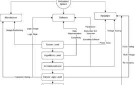
Low power design is a system using a collection of techniques and methodologies for the purpose of optimizing battery life and reducing the overall power dissipation of the system. To optimize the power there are many low power techniques that depend on the level of the design selected, ranging from semiconductor technology to the higher…