
In the previous tutorials, we demonstrated how to communicate data with AWS IoT Core using an ESP32, Raspberry Pi and a computer or laptop. We also covered device-to-device communication through AWS IoT Core using an MQTT broker. In this project, we’ll demonstrate how to communicate with AWS IoT Core using JavaScript. The application developed in this…
Top AI domains and career paths in 2026

Artificial intelligence crossed a critical threshold in 2026. AI is no longer confined to research labs or narrow pilot programs. It sits at the strategic core of nearly every major industry, with global AI spending projected to exceed $2 trillion in 2026 alone. That is a 36% year-over-year increase. Enterprise adoption has reached 88%, though…
Interfacing actuators using MicroPython and NODEMCU (Part 5)
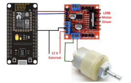
This tutorial series focuses on embedded system design using MicroPython and NODEMCU development board. In this series, you’ll learn embedded programming with MicroPython and how to interface different I/O devices, sensors, and actuators with the NODEMCU board. Interfacing different actuators In the previous tutorial, we learned how to interface a button and an LED with…
Embedded system design using MicroPython and NODEMCU (Part 4)
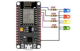
This tutorial series focuses on embedded system design using MicroPython and the NODEMCU development board. It introduces embedded programming concepts and shows how to interface different I O devices, sensors, and actuators with the NODEMCU board. Using an LED and button with NODEMCU The previous three tutorials in this series covered: MicroPython introduction NODEMCU pin…
How to enable device-to-device messaging on AWS IoT Core using MQTT
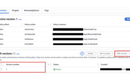
In the previous tutorials, we learned how to create setups for various devices, such as ESP32, Raspberry Pi, and computers on AWS IoT Core, create and attach AWS IoT policies, and communicate data in the form of MQTT messages between Internet-of-Things (IoT) devices and the AWS IoT platform. In IoT applications, devices must exchange data…
How to design a DIY “useless box” and learn the basics of electronics
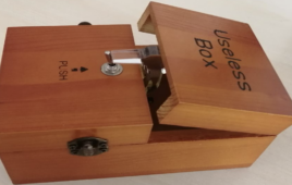
When you’re a beginner entering the world of Arduino and electronics, the options can feel overwhelming. There’s often genuine confusion about where to start. What can you build with a few servos and a microcontroller? How can you move beyond blinking LEDs into real interactive devices? Let us present the idea of the “useless box.”…
Würth Elektronik introduces WSEN-PDMS differential pressure sensor
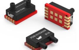
The WSEN-PDMS from Würth Elektronik is a differential pressure sensor with ±1 mbar accuracy and 16-bit resolution, supporting 3.0 V to 5.5 V operation with I²C, SPI and analog interfaces. The sensor provides calibrated pressure data with optional temperature output, operates from −25°C to +85°C and includes CRC support for reliable communication. Available with multiple…
India’s top semiconductor startups of 2026
The coming decade will likely mark a significant phase in the development of India’s semiconductor industry. The country is pushing toward semiconductor self-sufficiency, gaining momentum through the Design Linked Incentive (DLI) scheme launched under the India Semiconductor Mission (ISM). This initiative offers financial support covering up to 50% of eligible expenses, along with EDA tool…
VHDL Tutorial – 11: Designing half and full-subtractor circuits

Note: it’s recommended to follow this VHDL tutorial series in order, starting with the first tutorial. In previous tutorial VHDL tutorial – 10, we had designed half and full-adder circuits using VHDL. In this tutorial, we will: Write a VHDL program to build half and full-subtractor circuits Verify the output waveform of program (digital circuit) with…
VHDL Tutorial – 12: Design a 8-bit parity generator and circuit checker
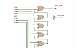
Note: it’s recommended to follow this VHDL tutorial series in order, starting with the first tutorial. In the previous tutorial VHDL tutorial – 11, we learned how to design half and full-subtractor circuits by using the VHDL. In this tutorial, we will: Write a VHDL program to build an 8-bit parity generator and checker circuits Verify…
VHDL tutorial 13: Design 3×8 decoder and 8×3 encoder using VHDL
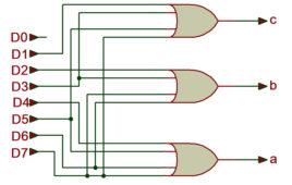
In the previous tutorial VHDL tutorial, we designed an 8-bit parity generator and 8-bit parity checker circuits using VHDL. (If you are not following this VHDL tutorial series one by one, you are requested to go through all previous tutorials of these series before going ahead in this tutorial) In this tutorial, We shall write…
VHDL Tutorial 14: Design 1×8 demultiplexer and 8×1 multiplexer using VHDL

In the previous tutorial VHDL tutorial, we designed 8×3 encoder and 3×8 decoder circuits using VHDL. (If you are not following this VHDL tutorial series one by one, you are requested to go through all previous tutorials of these series before going ahead in this tutorial) In this tutorial, We shall write a VHDL program…
VHDL Tutorial 17: Design a JK flip-flop (with preset and clear) using VHDL

Note: it’s recommended to follow this VHDL tutorial series in order, starting with the first tutorial. In the previous tutorial – VHDL tutorial 16 – we designed a D flip-flop circuit by using VHDL. For this project, we will: Write a VHDL program to build a JK flip-flop circuit Verify the output waveform of the program…
VHDL Tutorial 18: Design a T flip-flop (with enable and an active high reset input) using VHDL

Note: it’s recommended to follow this VHDL tutorial series in order, starting with the first tutorial. In the previous tutorial, VHDL tutorial – 17, we designed a JK flip-flop circuit by using VHDL. For this project, we will: Write a VHDL program to build the T flip-flop circuit Verify the output waveform of the program (the…
Getting started with MicroPython and NODEMCU (ESP8266 – 12E) Part 3
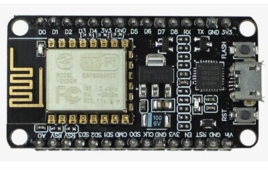
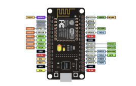
This tutorial series focuses on embedded system design using MicroPython and the NODEMCU development board. You’ll learn embedded programming with MicroPython and how to interface common I/O devices such as sensors and actuators with the NODEMCU board. In the first two tutorials, we covered the software (MicroPython) and the hardware (NODEMCU) used throughout this series.…
How to use MicroPython and NODEMCU for embedded system design: Hardware (Part 2)
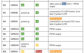
This tutorial series focuses on embedded system design using MicroPython and NODEMCU development board. It covers embedded programming with MicroPython and demonstrates how to interface different I/O devices, sensors, and actuators with NODEMCU board. The first article introduced MicroPython, including its features, program structure, and basic examples for interfacing simple I/O devices such as LED,…
Introduction: MicroPython for embedded system design on NODEMCU (Part 1)
This tutorial series focuses on embedded system design using MicroPython and NODEMCU development board. You’ll learn embedded programming with MicroPython and how to interface different I/O devices, sensors, and actuators with NODEMCU board. Arduino board, Arduino IDE, and C/C++ language (used in Arduino programming) are among the most popular and widely used tools in embedded…
How to design a portable, automated color vision test using ESP32

In this project, we’ll design a dual ESP32–based automated test system that offers a smart, low-cost solution to a common challenge in color vision screening. By replacing printed charts and manual supervision with an interactive, automated test, it makes color vision assessment more accessible. Simple to use and fully self-contained, the device helps identify color…
How to connect a computer to AWS IoT Core

In the previous tutorial, we connected a Raspberry Pi to AWS IoT Core and exchanged data between the cloud platform and the Raspberry Pi using MQTT. In many embedded applications, Internet-of-Things (IoT) devices are controlled or monitored through a desktop application. For that reason, it’s often useful to configure a computer (whether it’s a Windows…
How to design a weighing scale using ESP32

In this DIY circuit, we’ll build a simple yet effective digital weight scale using the Arduino platform, ESP32, an HX711 load cell amplifier, and an OLED display. This setup provides an accurate and user-friendly way to measure and visualize weight. The project can be further expanded by adding features, such as data logging, wireless communication,…