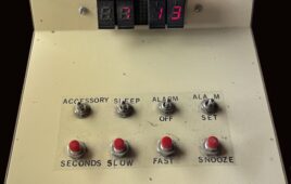
Look inside this one-chip clock built from surplus parts. With the case open, replacing parts waiting to fail seemed like a good idea. In my second year at WPI, I found myself in “B term” where I had a scheduling problem. Being as WPI operates on a four-term academic year, I couldn’t find a one-term…
How to design a security system that sounds like a guard dog
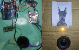
It’s been said that one of the best home security systems is owning a dog. In this do-it-yourself (DIY) circuit, we’ll design a unique system that lets you take advantage of a guard dog for security without ever needing to walk or feed it. This DIY system “barks” like a dog whenever motion is detected…
How to choose an inductor when designing a dc-dc converter
Inductors are simple components in electronic devices that perform tasks like cleaning up electrical signals, helping with timing, and managing power. They store energy in magnetic fields when electricity flows through them and releases them back into the circuit. Inductors resist sudden changes in the flow of electricity, pushing back “spikes” by creating an electrical…
How to design a lab power supply at home
The voltage requirements for different circuits vary much like microcontroller-based circuits require 5 V, motor controller or relay driver circuit requires 12 V, and other digital circuits require 3.3 V. If a circuit fails to receive its rated voltage and current, it will not work properly. So, it often makes sense to use a variable…
Simple overhead tank water level controller without an MCU
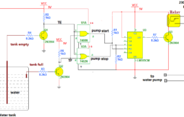
In this project, we will learn to create an automatic water pump system circuit that switches ON and OFF based on the water level in the tank. Basic idea The given project demonstrates a simple circuit built using digital logic gates, IC NE555, transistors, and a few additional components that sense the water level in…
Simple Door Alarm

You can use this Simple Alarm to protect the door or Window. It gives a loud beep and switch on the room light when an intruder/burglar attempts to breaks the door lock. The alarm functions only after 5 minutes to confuse the intruder. Working of this burglar alarm circuit is simple. IC1 is used to…
Electronic Guard to Protect Electronic Devices
This circuit can protect your Electronic devices like TV from inrush current. Very high spikes can develop at power on due to sparking in the switch and more serious effects occur when power resumes after a power failure due to high magnetic field in the distribution transformer. When we keep the TV in standby mode through…
Electronic Circuit Breaker
This circuit can sense the overload condition and breaks the power if the load increases above the set point. It is an ideal circuit to protect Uninterrupted Power Supply devices like Inverter.Let us see its working …The Optocoupler MCT2E and the Resistor R3 (1 Ohm 10 Watts) will do the trick. The Optocoupler has an LED and a Phototransistor inside with connecting leads. The LED of MCT2E is connected parallel to the resistor R3 with a current limiter R2 for the LED. The phototransistor of Optocoupler is connected to the transformer derived 9 volt DC through the current limiter R1. The load is connected through the Common and NC contacts of the relay. So it will work normally at power on.
Optical Toggle (Circuit to switch on / off the room light using TV remote)
This light triggered circuit can be used to turn on / off a load such as lamp through the IR rays from a remote or light from a torch. This is an ideal circuit to switch on / off the room light using TV remote while watching the TV .The circuit uses a Phototransistor and…
Variable power supply from fixed voltage regulator
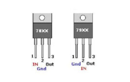
Voltage regulator is a device which provides fix output voltage in spite of the variable input voltage supplied. It is a three terminal device. Voltage [[wysiwyg_imageupload::]]regulator basically comes in two different series: 78XX and 79XX. Voltage regulator under 78XX series are designed for positive inputs i.e. if while 79XX series are designed for negative inputs.
Power Supply Resumption Alarm

The circuit which is shown here is too easy circuit. In this circuit IC1 is mounted in a unusual mode. At the time when power resumes, pin 2 of IC1 which is through capacitor C1 is grounded goes low and pin 3 of same IC switches to high. In turn of this pin 4 of IC1 which is a reset pin switches to high state for approximately 10 seconds. When the voltage at C1 reaches to 2/3 of the supplied voltage, capacitor starts discharging and output switches to low, grounding the pin 4 which is a reset pin and hence the fell circuit move out of action.
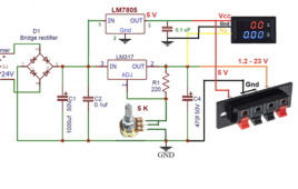
Variable power supply and charger with emergency light
A simple circuit of variable power supply and charger is described here. It is useful when the main power supply is available or when there is no power supply.This circuit can be used for testing electronic projects at your work bench. It can be used to charge your mobile battery. It can be used as an emergency light. In this circuit you can take outputs by flipping the different switches according to your requirement. Engage switch S3 if you want a variable power supply as output. For variable power supply, we have used variable voltage regulator LM317whichis a 3 terminal adjustable positive voltage regulator. It will provide an output voltage in the range of 1.2V to 37V. For obtaining different voltages, adjust the variable resistor to see the output on the multimeter and set the required voltage. Range of power supply varies from 1.5V-12V.
Un-interruptible Bench-top DC Power Supply With Display
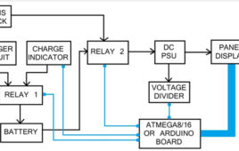
This tutorial explains how to make your own power supply unit for all your electronics and embedded system experiments. It also has a backup battery which will be used in case of power cuts and a display.
Smart Capacitor power supply
This capacitor power supply can deliver 12 volt DC and 100 mA current to power low current devices. It is provided with surge protection and is totally isolated from mains supply using two capacitors in the phase and neutral lines. So the connected device is safe even if the phase and neutral lines changes. Transformer…
FM Transmitter Bug: Learn how to Make one
The proposed simple electronic spy Bug circuit is basically a high gain amplifier using the IC 741 as the heart of the circuit and also a couple of high gain output transistors. The IC 741 if configured as a non-inverting amplifier which performs the function of a pre-amplifier stage. The gain of this IC 741 preamplifier stage may be varied as desired, using the pot across its input and output pin outs. The gain setting is used to set the sensitivity of the amplifier and is set to maximum so that even low volume speech conversation may be picked through it. The mic at the input transforms sound vibrations into minute electrical pulses, which is further amplified by the IC 741 to suitable levels before applying it to the output amplifier stage consisting of a standard DARLINGTON stage. This Darlington stage is made using a couple of high gain transistors bc107A’s.
Performing Experiments With LM358
In this project a protoype circuit which can switch on the device when the light falls on it. For this I will use LM358 IC which is operational amplifier. I have made the circuit with LDR and few more components. But when I interchange the LDR with photodiode, phototransistor and transistor (L14F1) my circuit works well without changing any other components. Before understanding the circuit which I have developed, first let’s have a look on the components used in the circuit.LM358 consists of two independent, high gain operational amplifiers in one package. Important feature of this IC is that we do not require independent power supply for working of each comparator for wide range of power supply. LM358 can be used as transducer amplifier, DC gain block etc.
Exhaust Fan Circuit Diagram

Many of us have modular kitchen which have chimney to extract smoke out so that smell of smoke will not fill in kitchen and avoids the harmful effects of smoke on furniture and kitchen utensils. But sometimes it happens we forget to switch on the chimney which results in smoke in kitchen and sometimes we forget to off the chimney leading to the wastage of electricity and money. So to solve this problem we have described a circuit which will switch on the fan automatically when smoke reaches to point and off the fan automatically.You can also use this circuit while soldering because as we know solder fumes are not good for health so it will on the fan to extract the smoke present in room leaving smoke free area.
Shooting Game Using IC555

This is a simple shooting game comprising of an infrared pulse emitter and receiver. There are 8 white leds and one green led which will light up periodically. The player has to shoot at the receiver when the green led lights up. This is a simple beginner’s project and can be used to make more complicated projects like “LASER TAG GAME”. Infrared gun (transmitter) for this electronic game is built around IC1 timer (NE555) wired as an astable multivibrator with a centre frequency of about 35 kHz. The receiver circuit has 3 main ICs – 2 NE555s (one wired as an astable multivibrator and the other for monostable operation) and 1 CD4017B (decade counter). These circuits can be modified to make “LASER TAG GAME”. Read more to find out how IC555 is used in this circuit and how it works.
Circuit Design: Pulse Amplitude Demodulation

The simple pulse modulation technique called Pulse Amplitude Modulation (PAM) proved to be more power efficient than the PWM and consumes constant power for individual pulses like PPM. In PAM the amplitude of the individual pulses are varied according to the amplitude of the modulating signals. The PAM modulator and demodulator circuits simple compared…
RGB Bulb using NE555
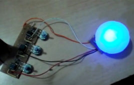
RGB bulb means bulb made up of three LEDs – RED, GREEN and BLUE. It generates light of many different colours. As we all know RED, GREEN and BLUE are three primary colours and all other colours can be generated by mixing these 3 colours in different amount. So in RGB bulb the intensity of RED, GREEN and BLUE LEDs are varied – means the amount of RED, GREEN and BLUE colours are varied to generate different colour or shade of different colour.The intensity of LED is varied using PWM generated by NE555 IC. NE555 chip generates PWM when it is connected in astable mode. So three NE555 ICs are used to vary the intensity of three LEDs – RED, GREEN and BLUE.