In the previous tutorial, advantages of UDP protocol over TCP/IP in IoT applications were discussed. The UDP protocol has a small overhead of 8 bytes which makes it more suitable for use in the Internet of Things. In this project, the application of UDP protocol in IoT will be demonstrated. In this project, an ESP8266 Wi-Fi modem will be configured as UDP server and a laptop will be used as UDP Client. Both Client and server will be co-located communicating through same Wi-Fi router so, the ESP board will act as a local server. The UDP Client could send data to the server on a particular port with the help of an application – Packet Sender.
The ESP module working as server checks for the UDP packet received from the client on a particular port. When a valid packet is arrived, an acknowledge packet is sent back to the client to the same port it has been sent out. In response to receiving packet and sending acknowledgement, the ESP modem switches on an LED as visual indication of successful Client-Server Communication. This application is very useful as it demonstrates server/client communication over UDP protocol.
It can be said that the IOT device designed in this project is a simple UDP server with LED indicator. It is designed by interfacing an LED with the ESP-8266 Wi-Fi module. The Wi-Fi module as well as LED light are powered continuously with the help of a USB to Serial Converter. The Wi-Fi module needs to loaded with a firmware that could receive data over UDP protocol and respond with an acknowledgement. The Arduino UNO is used to flash the firmware code on the ESP8266 module. The ESP module can also be flashed with code using a FTDI converter like CP2102. The firmware itself is written in the Arduino IDE.
Component Required –

Fig. 1: List of components required for UDP Protocol based Client Server Communication
Software Required –
• Arduino IDE
Block Diagram –
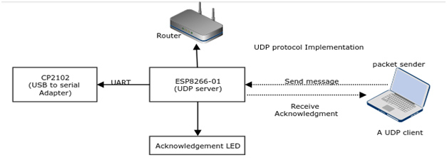
Fig. 2: Block Diagram of ESP8266 UDP Server and Packet Sender UDP Client Communication
Circuit Connections –
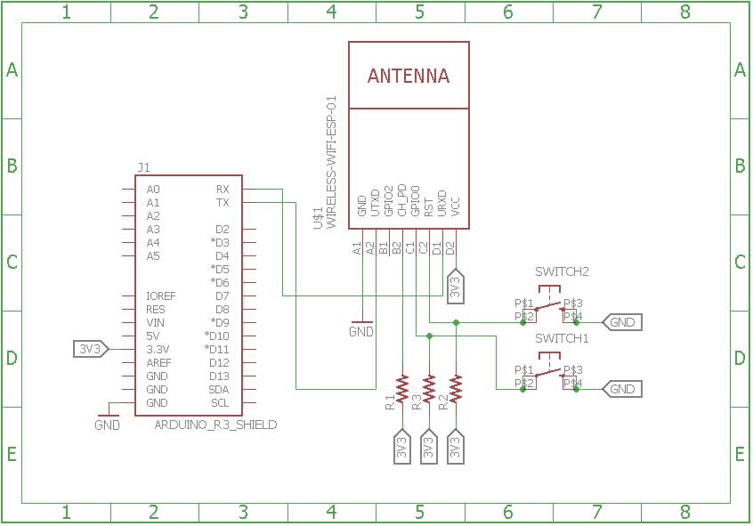
First of all, the ESP8266 board needs to be loaded with the firmware code. In this tutorial, the firmware code is written using Arduino IDE. It is loaded to the ESP8266 board using the Arduino UNO. A generic ESP8266 board is used in this project. This board does not have any bootstrapping resistors, no voltage regulator, no reset circuit and no USB-serial adapter. The ESP8266 module operates on 3.3 V power supply with current greater than or equal to 250 mA. So, CP2102 USB to serial adapter is used to provide 3.3 V voltage with enough current to run ESP8266 reliably in every situation.
The ESP8266 Wi-Fi Module is a self contained SOC with integrated TCP/IP protocol stack that can access to a Wi-Fi network. The ESP8266 is capable of either hosting an application or off loading all Wi-Fi networking functions from another application processor. Each ESP8266 module comes pre-programmed with an AT command set firmware. The module comes available in two models – ESP-01 and ESP-12. ESP-12 has 16 pins available for interfacing while ESP-01 has only 8 pins available for use. The ESP-12 has the following pin configuration –
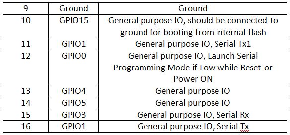
Fig. 3: Table listing pin configuration of ESP8266 ESP-12 Module

Fig. 4: Table listing pin configuration of ESP8266 ESP-12 Module
The ESP-01 model is used in the project. The ESP-01 model has the following pin configuration –
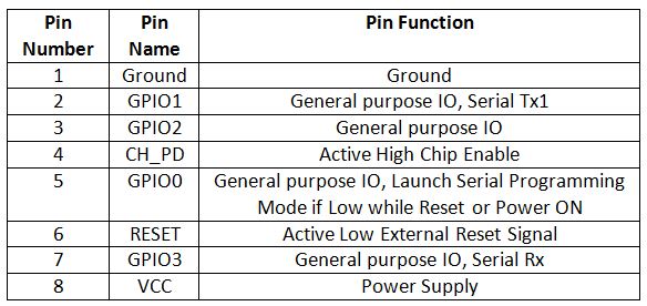
Fig. 5: Table listing pin configuration of ESP8266 ESP-01 Module
The Chip Enable and VCC pins of the module are connected to the 3.3 V DC while Ground pin is connected to the common ground. The chip enable pin is connected to VCC via a 10K pull up resistor. The RESET pin is connected to the ground via a tactile switch where the pin is supplied VCC through a 10K pull up resistor by default. The Tx and Rx pins of the module are connected to the RX and TX pins of the Arduino UNO. The GPIO-0 pin of the module is connected to ground via a tactile switch where the pin is supplied VCC through a 10K pull up resistor by default.
These pull-up resistors act as voltage divider circuit which protects the ESP8266 board from high voltage. The Arduino board operates at 5V as well as 3.3 V while ESP8266 operates at 3.3 V. Though the Arduino board itself is powered via its 3.3 V supply pin, this voltage divider circuit further adds protection from any voltage surge. The use of pull-up resistors increases the stability of the circuit. With these circuit connections, the Arduino board itself act as USB to Serial Adaptor. The circuit connections between the Arduino UNO and ESP8266 module for boot loading can be summarized as follow –
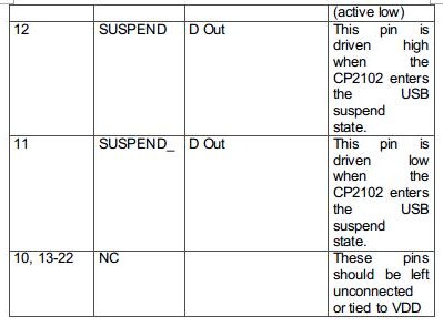
Fig. 6: Table listing circuit connections between Arduino and ESP8266 Module
During compilation of the code, the GPIO0 and RESET switches must be pressed. For uploading program, the RESET switch must be released while the GPIO0 programming switch must be left pressed, so that the ESP can enter in programming mode. After uploading the code, the programming switch should also be released as well.
Write the firmware code in the Arduino IDE and connect the Arduino board with the PC via USB cable. Open Arduino IDE and go to Tools->Port and select the Arduino board (Arduino UNO). It may look like /dev/ttyABM0 (Arduino/Genuino Uno). Select the correct port name. The port name can be different in different IDE setups. Then Open Serial monitor in the Arduino IDE by navigating to Tools->Serial Monitor and set the baud rate to 115200 bauds per second. Pass ‘AT’ and ‘AT+GMR’ commands to test the connection between the Arduino and ESP-01 module. Try different settings for the ‘Line ending’ option of the serial monitor like Both NL & CR. Try different combinations until the ESP module starts interacting correctly with the serial monitor.
Download Python, PIP and ESPtool. Erase the pre-loaded firmware if the ESP module has any. Flash the firmware code to the ESP-01 module by writing the commands in serial monitor as instructed for the ESPtool. Check out the following link to write proper command for flashing the firmware code using ESPtool-
For uploading program, the RESET switch must be released while the GPIO0 programming switch must be left pressed. After loading the code, the programming switch should also be released as well. In this way, the firmware code can be loaded to the ESP8266 using the Arduino board as FTDI converter. It must be noted that every GND needs to be common to complete the circuit. The GPIO2 is alternative TX for bootloader mode.
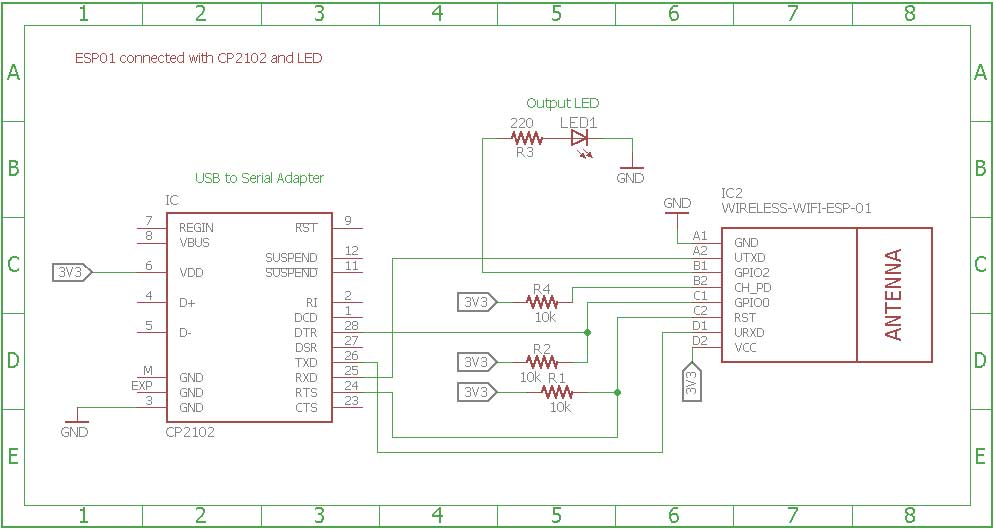
Remove the connections. Now the ESP module is ready to be installed in the project circuit. In the project circuit, the ESP8266 is interfaced with the CP2102 adapter and an LED.
The CP2102 is a single chip USB to UART Bridge. It is used to provide power supply to the ESP module. It can be used for boot loading as well. A CP2102 IC has the following pin configuration –

Fig. 7: Table listing pin configuration of CP2102 IC

Fig. 8: Table listing pin configuration of CP2102 IC

Fig. 9: Table listing pin configuration of CP2102 IC
The ESP board is connected to the CP2102 for boot loading mode and usage purpose. For boot loading, the ESP-01 TX pin is connected to RX pin of CP2102 and ESP’s RX pin is connected to the TX of CP2102 so that they both can send and receive the data. The ESP8266-01 needs 3.3 V power supply so ESP’s VCC is connected to the 3V3 of CP2102 and GNDs of both need to be connected to each other. The reset pin of ESP8266 along with 10k pull-up resistor (bootstrap resistor) is connected to the RTS pin of CP2102. The GPIO0 is a programming pin which is used to end the ESP-01 into programming mode. The GPIO0 along with 10K pull-up resistor is connected to DTR pin of CP2102. The CHPD pin of ES-01 is pulled-up with 10K resistor. The circuit connections between the ESP module and the CP2102 are summarized in the following table –
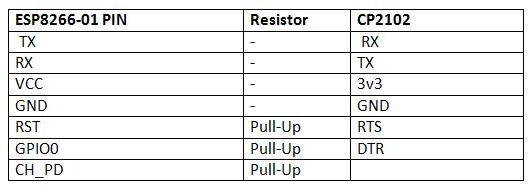
Fig. 10: Table listing circuit connections between ESP8266 ESP-01 Module and CP2102 IC
After connecting the ESP module with the CP2102 adapter, the adaptor must be connected to the PC and the ESP module must be loaded with the firmware code in the similar manner as is demonstrated with the Arduino.
After loading the code, the ESP module will automatically access the Wi-Fi point with the SSID given in the firmware. An LED is connected to the ESP module. The LED’s anode pin is connected to the GPIO2 with 220 ohm series resistor and cathode pin is connected to the GND. The ESP module is now ready to receive data over UDP protocol via Wi-Fi Router and will control LED to indicate successful communication with the UDP Client.
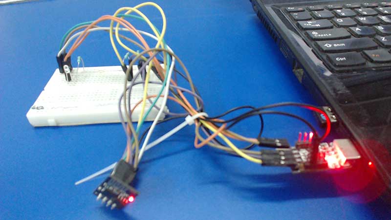
Fig. 11: Prototype of ESP8266 UDP Server
On the laptop, Packet Sender is used as UDP Client. In fact, any other Client that supports UDP can be used. For setting up packet sender as a UDP client, First, open the packet sender and write down the input parameters in the required fields. In the name field, any name can be written so that client can be uniquely identified. In ASCII field, write the actual datagram has to be sent and in address, write the IP address of the UDP server and the port on which server is listening. It is that simple. Install and launch the Packet Sender application. Fill in required fields and the client is now ready to send the datagram to server.
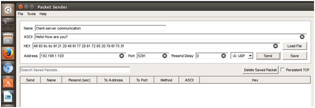
Fig. 12: Screenshot of Packet Sender UDP Client
How the circuit works –
The ESP modem act as UDP server in this setup. It is loaded with a firmware that can receive data on UDP protocol and in response send back an acknowledgement on the same port. The Laptop which is acting as UDP Client sends the datagram using packet sender application. The firmware code on the ESP modem light up an LED after successful communication with the UDP Client.
In the firmware code of the ESP8266 based UDP server, the Wi-Fi connection is initiated with the available router and the UDP connection is setup using standard library functions. A library named WifiUDP.h is imported in the ESP code for managing the UDP connection and receiving data over it. Once the UDP packet is successfully received, the code sends an acknowledgement on the same port and set the LED connected pin to HIGH. The following flow-chart demonstrates the UDP connection and data management on the ESP8266 UDP server –
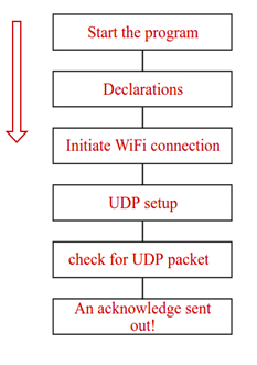
Fig. 13: Flowchart of ESP8266 UDP Server Connection and Data Management
On the laptop side, the UDP connection and data delivery is managed solely by the Packet Sender application.
Programming Guide –
The ESP8266 modem is programmed to operate as UDP server. In the ESP code, WifiUDP.h is imported to manage the UDP connection and receive data over it. A wifiUDP object is instantiated for programming of UDP routines. The UDP port on which the server is listening is specified. For receiving any message, a buffer is set up so that no message is missed. When client sends the message, the server will acknowledge the client by sending another packet.
WiFiUDP Udp;
unsigned int localUdpPort = 5291;
char incomingPacket[255];
char replyPacekt[] = “Welcome here!”;
After declaration, a Wi-Fi connection is initiated. The ESP8266 Wi-Fi is used to connect the server to the access point (Internet). The following code declares the Wi-Fi SSID and password.
const char* ssid = “Virus Detected”;
const char* password = “123456789”;
The following function is used to initiate the Wi-Fi connection.
WiFi.begin(ssid, password); //start the ESP8266 connection with the network
After connection to the Internet is established, the server keeps on listening for incoming packets on the specified port using the following function –
Udp.begin(localUdpPort);
In this way, the connection of server to the Internet is established on the specified port. Now server is ready to listen for any message. When the server receives the client request and it respond according to the received request. The server will be waiting for receiving the incoming packets. When server receives the packet, it stores it into buffer and uses for further process. In this whole process, once a packet is received, the code will print out the IP address and port of the sender as well as length of the received packet. If the packet is not empty, its content will be printed out as well. The following code manages to receive the packets –
//listening for incoming UDP packets
int packetSize = Udp.parsePacket();
//Received Packet? Yes!
if (packetSize)
{
Serial.printf(“Received %d bytes from %s, port %dn”, packetSize,
Udp.remoteIP().toString().c_str(), UDP.remotePort());
int len = Udp.read(incomingPacket, 255);
if (len > 0)
{
incomingPacket[len] = 0; }
Serial.printf(“UDP packet contents: %sn”, incomingPacket);
Whenever a message is sent from UDP client, the UDP server acknowledges to that client by sending acknowledgement message. For each received packet, an acknowledge packet is sent using the following functions –
Udp.beginPacket(Udp.remoteIP(), Udp.remotePort());
Udp.write(replyPacekt);
Udp.endPacket();
It must be noted that the reply is sent to the IP and port of the sender by using Udp.remoteIP() and Udp.remotePort().
So, the server is waiting to receive the packets, when the client sends the packet, the server identifies it on the basis of IP address and port number then on receiving the packet, it notify the client by sending acknowledgement packet. In this way, server-client communication is established. On successful communication of delivery of data to it, the server set the LED connected pin to HIGH lighting up the LED to visually indicate successful UDP communication.
In the next tutorial, learn about CoAP protocol.
You may also like:
Project Source Code
### //Program to #include#include const char* ssid = "Virus Detected"; const char* password = "techshlok"; int status_led = 2; WiFiUDP Udp; unsigned int localUdpPort = 5219; // local port to listen on char ReceivedMessage[255]; // buffer for incoming packets char Acknowledge[] = "Received your message: "; // a reply string to send back void setup() { Serial.begin(115200); pinMode(status_led, OUTPUT); Serial.println(); Serial.printf("Connecting to %s ", ssid); WiFi.begin(ssid, password); while (WiFi.status() != WL_CONNECTED) { delay(500); Serial.print("."); } Serial.println("Wi-Fi connected!"); Udp.begin(localUdpPort); Serial.printf("I am listening at IP %s, UDP port %dn", WiFi.localIP().toString().c_str(), localUdpPort); } void loop() { int packetSize = Udp.parsePacket(); if (packetSize) { // receive incoming UDP message Serial.printf("Received %d message from %s, port %dn", packetSize, Udp.remoteIP().toString().c_str(), Udp.remotePort()); int len = Udp.read(ReceivedMessage, 255); if (len > 0) { ReceivedMessage[len] = 0; } Serial.printf("UDP message: %sn", ReceivedMessage); digitalWrite(status_led, HIGH); delay(1000); digitalWrite(status_led, LOW); // send back a reply, to the IP address and port we got the packet from Udp.beginPacket(Udp.remoteIP(), Udp.remotePort()); Udp.write(Acknowledge); Udp.endPacket(); } } ###
Circuit Diagrams
Project Video
Filed Under: Featured Contributions, IoT, IoT tutorials, Tutorials
Filed Under: Featured Contributions, IoT, IoT tutorials, Tutorials




Questions related to this article?
👉Ask and discuss on Electro-Tech-Online.com and EDAboard.com forums.
Tell Us What You Think!!
You must be logged in to post a comment.