Increasingly popular battery-powered consumer and industrial applications — such as cordless power tools and service robots — demand reliable, cost-effective, and energy-efficient motor control solutions that meet the highest safety standards. To enable the next generation of innovative and high-performance battery-powered products, Infineon Technologies is expanding its EiceDRIVER product portfolio of three-phase gate driver ICs. The fully…
MEAN WELL launches new series of portable, enclosed inverters
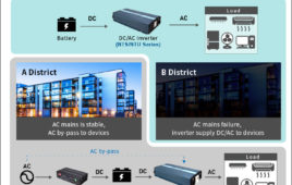
MEAN WELL recently launched the NTS-250P/400P, NTS-300/450, NTS-750 series of DC-AC pure sine wave inverters. Now, the company is presenting its new, NTS/NTU-1200 series of 1200W, external and portable enclosed inverters. These inverters are designed to replace the previous TS-1000 generation, offering improvements including an increase of 200W, a smaller case size, easier operation of…
Vishay launches industrial, thin-film wraparound chip resistor
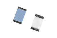
Vishay Intertechnology, Inc. has introduced a new high-precision, thin-film wraparound chip resistor for industrial, medical, military, and aerospace applications. The Vishay Sfernice P2TC offers a tight TCR of ± 2 ppm/° C over wider resistance and temperature ranges — and in more case sizes with higher power ratings — than competing devices. Available in five case sizes…