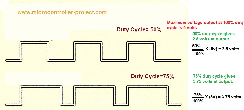
Engineers Garage

  • Projects and Tutorials
    • Circuit Design
    • Electronic Projects
      • 8051
      • Arduino
      • ARM
      • AVR
      • PIC
      • Raspberry pi
      • STM32
    • Tutorials
    • Components
  • Articles
    • EG Blogs
    • Insight
    • Invention Stories
    • How to
    • What Is
    • News
      • EE Design News
      • DIY Reviews
      • Guest Post
      • Sponsored Content
  • Forums
    • EDABoard.com
    • Electro-Tech-Online
    • EG Forum Archive
  • Digi-Key Store
    • Cables, Wires
    • Connectors, Interconnect
    • Discrete
    • Electromechanical
    • Embedded Computers
    • Enclosures, Hardware, Office
    • Integrated Circuits (ICs)
    • Isolators
    • LED/Optoelectronics
    • Passive
    • Power, Circuit Protection
    • Programmers
    • RF, Wireless
    • Semiconductors
    • Sensors, Transducers
    • Test Products
    • Tools
  • EE Resources
    • DesignFast
    • LEAP Awards
    • Oscilloscope Product Finder
    • Video
    • White Papers
    • Webinars
  • EE Learning Center
  • Women in Engineering

Led Brightness controlled with 8051(89c51,89c52) Microcontroller

July 28, 2019 By EG Projects

Controlling led brightness or fading an led using 8051(89c51,89c52) microcontroller is not an easy task. In depth knowledge of 8051 microcontroller timers and their registers is required to fade or control led brightness with 89c51 microcontroller. So in this project/tutorial i am going to teach you how to fade an led with 89c51 microcontroller?

How to control led brightness?

To fade and control brightness of led we have to provide different voltage signal levels to led. Each voltage level glows led according to the voltage value. For example you have an led whose rating is 5 volt. To fade it we have to provide voltage ranging from 0.1 to 5 volts. At 5 volts input led will glow at its maximum brightness. Decreasing voltage from 5 will decrease the led brightness. If we speed up the brightness cycle then led will show a fading effect.

Typical led brightness control method

A variable resistor can easily fade an led by varying the resistance, if led is connected in series with it. Varying resistance increases or decreases the output voltage. Like we rotate the potentiometer/variable resistor of fan to speed up or lower the rotating speed of our home ceiling fan. With variable resistor/potentiometer its easy to control the brightness of led. But when we need to control brightness with microcontroller, its seems to be a hard task, because their is no variable resistor functionality in microcontroller. 

How to fade led using microcontrollers?

Best way to fade led using microcontrollers is to use PWM(Pulse width Modulation) technique. In pulse width modulation duty cycle of the signal is varied. Duty cycle is the ratio of active period to non-active period. For each duty cycle output voltage is different. Duty cycle of 100% gives maximum voltage. When duty cycle decreases from 100%, output voltage also decreases. Here is a simple picture that clears you about duty cycle game.
PWM Duty Cycles

PWM Duty Cycles

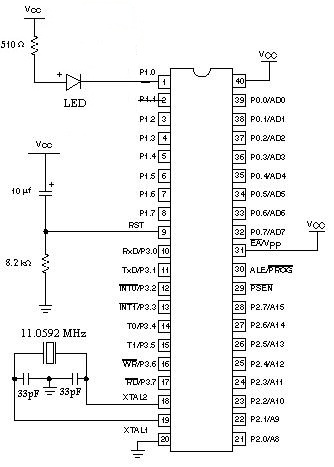
89c51 led fading circuit diagram

I connected led to Port-1 Pin#0 of 89c51 microcontroller. Led is connected in series to a 510 ohm resistor. 11.0592 MHz crystal is used to provide clock to 8051 microcontroller. Crystal is attached to 8051 microcontroller in parallel to two 22pf capacitors. Circuit diagram of the project is given below.
Fading led using PWM technique with 89c51 microcontroller

Fading led using PWM technique with 89c51 microcontroller

PWM(pulse width modulation) signal generation using 89c51 microcontroller timers

To generate PWM using microcontroller you have to utilize its timer. In the code below i used timers to generate PWM. 8051 series microcontrollers have two build in Timers. You can use them as 16-bit or 8-bit. Since 8051 is an 8-bit microcontroller then how could we use timer in 16-bit mode. Their are two 8-bit registers dedicated for timers you can combine them to use timer in 16-bit mode. These registers are THx and TLx. To learn more about 8051 Timers, registers associated with them and how to use timers just go through a small tutorial.
How to use internal Timers of 8051(89c51,89c52) microcontroller?  

I am using Timer-0 of 89c51 microcontroller in 16-bit mode. Their are two variables most important in my code. They are high-low and h1-l1. high-low is associated with the high period of signal and h1-l1 is associated with low period of the signal. high and h1 are associated with TH0 register of 89c51. I am generating 20 different waves for achieving pwm. 20 different waves means 20 different duty cycles. In the code a for loop is running 20 times, duty cycle logic is placed in that for loop. Initially duty cycle is low for a little duration then it goes high and high up to 100%. Actually timers are loaded with 20 different values and they run for 20 different values, but at a time timer runs on a single value. 

In the code initially TH0 is loaded with 0xFF(high) and TL0 with 0xFF(low), this combination is for high signal. Timer runs with this combination for 100 times and at the same time for low signal TH0 is loaded with 0xEB(h1) and TL0 0xFF(l1). TH0 is loaded with 0xEB because initially we want low signal for some long duration.  Now when this for loop runs, signal for high wave increases and signal for low wave decreases. Due to which we receive a PWM signal as output on the pin and we can see led fading and brightness is increasing and decreasing continuously.

Note: 0xEB gives a gap of 0xFF-0xEB(hexadecimal)=20(decimal). So we are increasing and decreasing our signal levels equally on both sides(High and Low). h1 increases from 0xEB and it goes to 0xFF after 20 increments and high decreases from 0xFF to 0xEB after 20 decrements. You can increase the PWM frequency by using a crystal of high value.    

Download the Project Code and HEx file. Code is written in C language and keil compiler is used to compile the Code. Folder also contains the simulation of the project. Simulation is made is Proteaus 8.0. Please give us your feed back on the project.
Fading Led with 89c51 microcontroller

Related Articles Read More >

A Bluetooth-controlled datalogger robot
touch bell push
How to design a touchless bell push using Arduino
SMS-enabled scrolling message board using Arduino
Interfacing stepper motor with 8051(89c51,89c52 ) microcontroller

Featured Tutorials

  • Screenshot of Raspbian OS on Raspberry Pi RPi Python Programming 03: Raspberry Pi as Linux System
  • Raspberry Pi Models RPI Python Programming 02: Raspberry Pi Models
  • Raspberry Pi 4 RPi Python Programming 01: Introduction to Raspberry Pi 4
  • RPi Python Programming 05: Introduction to Python
  • RPi Python programming 04 RPi Python programming 04: Setting up Raspberry Pi Linux computer
  • Python Basics RPi Python Programming 06: Python basics

Stay Up To Date

Newsletter Signup

EE Training Center Classrooms

“ee

“ee

“ee

“ee

Recent Articles

  • New Vishay Semiconductors increase efficiency of high-frequency applications
  • TI launches industry’s top wireless battery-management solution
  • AVX releases new series of embedded, highly sensitive Wi-Fi antennas
  • Nuvoton offers a secure storage MCU for multi-segments
  • Refrigerator Compressor Design Achieves High Energy Efficiency Ratings Using a Digital Signal Controller (DSC)
...

RSS EDABOARD.com Discussions

  • Rippe current rating of aluminium electrolytic capacitor is very low.
  • Why do some op amps have a higher GBW than what the unity gain-bandwidth is?
  • Stacked Diodes ?
  • dsPIC33f ADC reading voltage help
  • What the best way to store data of size ( 90,000 * 32) bit (taken from a text file) using VHDL?

RSS Electro-Tech-Online.com Discussions

  • Engine Temperature using an AD590 on the Oil Pressure Wire to the engine
  • Automotive 6 Volt Generator Transistor Voltage Regulator
  • Jon's Imaginarium - Microchip FilterLab Program and Graph Paper Printer Program by Dr. Philippe Marquis
  • Touch circuit sound, led. 555 timer
  • Dust extractor remote switch
Engineers Garage
  • Analog IC TIps
  • Connector Tips
  • DesignFast
  • EDABoard Forums
  • EE World Online
  • Electro-Tech-Online Forums
  • Microcontroller Tips
  • Power Electronic Tips
  • Sensor Tips
  • Test and Measurement Tips
  • 5G Technology World
  • About Us
  • Contact Us
  • Advertise

Copyright © 2021 WTWH Media LLC. All Rights Reserved. The material on this site may not be reproduced, distributed, transmitted, cached or otherwise used, except with the prior written permission of WTWH Media
Privacy Policy | Advertising | About Us

Search Engineers Garage

  • Projects and Tutorials
    • Circuit Design
    • Electronic Projects
      • 8051
      • Arduino
      • ARM
      • AVR
      • PIC
      • Raspberry pi
      • STM32
    • Tutorials
    • Components
  • Articles
    • EG Blogs
    • Insight
    • Invention Stories
    • How to
    • What Is
    • News
      • EE Design News
      • DIY Reviews
      • Guest Post
      • Sponsored Content
  • Forums
    • EDABoard.com
    • Electro-Tech-Online
    • EG Forum Archive
  • Digi-Key Store
    • Cables, Wires
    • Connectors, Interconnect
    • Discrete
    • Electromechanical
    • Embedded Computers
    • Enclosures, Hardware, Office
    • Integrated Circuits (ICs)
    • Isolators
    • LED/Optoelectronics
    • Passive
    • Power, Circuit Protection
    • Programmers
    • RF, Wireless
    • Semiconductors
    • Sensors, Transducers
    • Test Products
    • Tools
  • EE Resources
    • DesignFast
    • LEAP Awards
    • Oscilloscope Product Finder
    • Video
    • White Papers
    • Webinars
  • EE Learning Center
  • Women in Engineering