Alarm Clock, Timer and Stopwatch are common time-keeping features. These functions are so frequently used that it is difficult to imagine modern life without a time-keeping application nowadays. Whether it is a scheduled wake up alarm, a stopwatch to track the time one has jogged or a timer and alarm to schedule office tasks, time-keeping is part and parcel of day-to-day life. This is an Arduino project demonstrating a complete time-keeping application. The project is a real-time clock and allows setting alarms, timers and running stopwatch.

Fig. 1: Prototype of Arduino and RTC DS1307 based Digital Clock and Alarm
It also displays real-time weather conditions with temperature and humidity indications as add-ons
The project has utilized RTC DS1307 for time-keeping and DHT11 sensor for fetching weather information. It is built on Arduino UNO and RTC used is internally powered through a button cell, so the project keeps track of real time and perform user-defined functions irrespective of the continuity of power supply to the circuit. The time and date, temperature and humidity values are displayed on a 16X2 LCD which also provides human interface to set alarm, timer and stopwatch. The users can feed inputs through a 4-switch keypad with switches for the following functions – Mode Selection, ENTER, Increment and SAVE buttons. A buzzer is connected to the Arduino board for realizing alarm and timer alerts.
The project runs under four modes of operations – :
1) Default Mode: By default, the project is set to display time, date, temperature and humidity information on the 16X2 LCD screen.
2) Alarm Mode: Here, user can set an alarm. The user enters this mode by pressing Mode selection button once and pressing the ENTER Button thereafter. He can first increase “Hours” value by pressing Increment button and skip to increase “Minutes” value by pressing the ENTER button again. After setting “Hours” and “Minutes” value the user can invoke alarm by pressing the SAVE button. To exit the alarm mode, Increment and mode selection buttons have to be pressed together.
3) Timer Mode: A timer setting mode can be entered by pressing the Mode selection button twice and pressing the ENTER button thereafter. The process for setting and saving time for timer is same as in alarm mode except that “Seconds” value can also be set in this mode. The user can exit the timer mode after setting time by just pressing the mode selection button once again.
4) Stopwatch Mode: To enter stopwatch mode, pressing mode selection button thrice and pressing the ENTER button thereafter works. Here pressing the SAVE button starts the stopwatch, pressing increment button pauses the stopwatch and pressing ENTER button again resets the stop watch. To exit the stopwatch mode, ENTER and Mode Selection buttons have to be pressed together.

Fig. 2: Image of Arduino and RTC DS1307 based Digital Clock and Alarm
Components Required
• Arduino UNO
• RTC module-DC1307
• 16×2 LCD
• 5v Buzzer
• BC 547 transistor
• 1K ohm resisters -7pcs
• Push to ON switch-4pcs
• Voltage regulator -7805
• LED -5mm RED- 2pcs
• DHT11 sensor
• 10K POT for LCD contrast

Fig. 3: Block Diagram of Arduino and RTC DS1307 based Digital Clock and Alarm
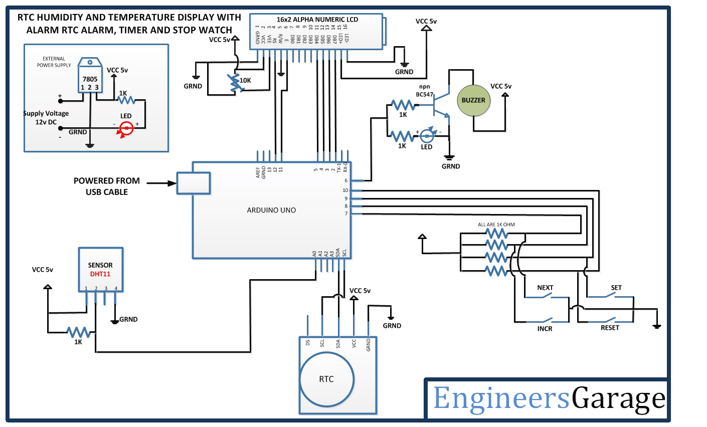
Circuit Connection
The major blocks of the circuit are as follow
1) Power Supply Circuit
2) RTC DS1307 Module
3) DHT11 Temperature and Humidity sensor
4) LCD Display
5) 4-switch keypad
6) Buzzer
7) Arduino Board
The Arduino UNO programmatically controls all the time-keeping functions of the application. All the components are interfaced to the Arduino board for the circuit to run. The circuit is connected in the following manner -:
1) Power Supply – The entire circuit runs on a 5V DC supply. A 12V battery is used to source power to the circuit. The 12V supply is stepped down to 5V by a 7805 voltage regulator. The pin 1 of 7805 receives 12V supply from anode and pin 2 is grounded. The output 5V is generated at pin 3 of the regulator. An LED is also connected in parallel to the output as a visual indicator of power supply.
2) RTC DS1307 Interfacing – The RTC DS1307 has a built in button cell that allows keeping track of real-time irrespective of the power supply. For interfacing with the Arduino board, SDA and SCL pins of the RTC are connected to the SDA and SCL pins of the Arduino UNO.
Learn more about interfacing and programming RTC with Arduino here
3) DHT11 Temperature and Humidity Sensor – This is a digital sensor with inbuilt capacitive humidity sensor and Thermistor. It relays a real-time temperature and humidity reading every 2 seconds as a digital output. The pin 1 and 4 of DHT11 are VCC and Ground respectively. The output is received from pin 2 of the sensor which is feed to A0 pin of the Arduino board through a 10K ohm pull up resistor.
4) LCD Display – The 16X2 LCD display is connected to the Arduino board by connecting its data pins to pins 2 to 5 of the Arduino board. The RS and E pin of LCD is connected to pins 12 and 11 of the Arduino UNO respectively. The RW pin of the LCD is grounded.
| LCD | Arduino Uno |
| RS | 12 |
| RW | GRND |
| E | 11 |
| D7, D6, D5, D4 | 2,3,4,5 respectively |
The standard code library for interfacing Arduino UNO and Arduino Pro Mini are used in the project to program LCD with the board. The code library works as expected. Learn more about LCD interfacing with the Arduino UNO.
5) 4-switch Keypad – The keypad here is a set of four push-to-on switches which are connected to 10, 9, 8 and 7 pins of the Arduino UNO through 1K ohm pull-up resistors. The switches connected at 10, 9, 8 and 7 pins works as SAVE, Increment, Enter and Mode selection buttons respectively. In the circuit diagram, SAVE, Increment, Enter and Mode selection buttons are designated by FIRST, SECOND, THIRD and MODE labels.
6) Buzzer – The buzzer is connected to pin 6 of the Arduino board. A common emitter NPN BC547 transistor circuit is used to relay signal from Arduino pin to the buzzer.

Fig. 4: Image showing message displayed on Arduino and RTC DS1307 based Digital Clock and Alarm
How the Circuit Works
As the circuit is powered up, Arduino runs initial code thereof preparing LCD screen for display output and fetches signals from RTC and temperature sensor. The project enters default mode. Some initial messages are flashed on the display screen. The readings from RTC and temperature sensor are digitally read at pins SDA-SCL and A0 respectively. The readings are saved to internal EEPROM and time, date, temperature and humidity values are displayed on the 16X2 LCD.
The user inputs are read through the 4-switch keypad. On pressing any switch, a LOW signal is detected at the respective pin connected through the switch. A detection of LOW signal from the switches prompts the code to run respective functions to enter other modes and setting or resetting time values.
The project enters alarm mode on detecting a single LOW signal at mode selection button followed by a LOW signal at ENTER button. The setting and resetting of time values is done by detecting LOW signals at increment and SAVE buttons in a pre-defined sequence. The time entered by the user is saved to internal EEPROM and compared to the real-time fetched from the RTC in a loop. When the user entered time matches the current time, a LOW signal is output at pin 6 of the Arduino board. This prompts to light up the LED connected in parallel to the buzzer circuit as visual indicator of alarm alert. In the buzzer circuit, on receiving a LOW signal at pin 6, the common emitter configured BC547 transistor gets short circuited allowing a flow of current from collector to emitter. The buzzer gets a ground at the collector end of the transistor and starts buzzing the alert. The alarm mode is terminated after the buzzer alert and LED signal. The program code allows to exit from the alarm mode on detection of LOW signals from increment and mode selection buttons simultaneously.
The timer mode is activated on detection of two continuous LOW signals at mode selection button and followed by a LOW signal at ENTER button. The setting and resetting of time values is again done by detecting LOW signals at increment and SAVE buttons in a pre-defined sequence. In timer mode, user is allowed to set the “Seconds” value as well. The user entered time is counted down by keeping a track of current time from the RTC. The countdown time is displayed on the LCD screen with the help of loop logic. When the countdown reaches zero value, again a LOW signal is activated on pin 6 of Arduino thereby running the buzzer and lighting up LED as explained above. Thereafter, the mode is terminated and resumes to the default mode.
The stopwatch mode is invoked on detection of three back to back LOW signals at mode selection switch followed by a LOW signal at ENTER button. The display at the LCD is reset to show zero time values. On detection of a LOW signal at SAVE button, stopwatch starts. The time user starts stopwatch is fetched from RTC and saved to the internal memory. In a loop the current time is fetched from the RTC and saved to internal memory. The current time is compared to start time and a time update is displayed accordingly on the LCD screen. If a LOW signal is detected at the increment button, the loop is stopped for until a start signal is received thereof stopping any time updates. Once the stopwatch has started, on detection of a LOW signal at ENTER button resets the time to zero and prompts to wait for a start signal. The mode is terminated on receiving LOW signals at ENTER and Mode selection buttons simultaneously. The termination of the mode resumes the default mode.
The time and date updates in any mode remain unaltered even if the power supply is interrupted because RTC DS1307 has an in-built button cell to keep RTC in sync. The temperature and humidity readings are updated every 2 seconds as DHT11 relays the digital readings out in that interval.
Programming Guide
The code uses standard open-source libraries of Arduino UNO. When the circuit is powered on, the Arduino loads standard libraries of LCD, EEPROM and RTC and import the functions used from the libraries.

Fig. 5: Screenshot of initialization in Arduino code for Digital Clock and Alarm
The Arduino board is initialized through a setup() function to start fetching real-time from RTC module, prepare LCD for display and activating input/output mode and HIGH/LOW signals at the pins interfaced with the keypad and buzzer circuit. Some initial messages are flashed through the LCD screen using print function of the LCD class. The RTC is checked and configured to relay current time and date.

Fig. 6: Screenshot of Setup Function in Arduino code for Digital Clock and Alarm
The RTC and DHT11 readings are saved to the internal EEPROM.

Fig. 7: Screenshot of EEPROM related Arduino code for Digital Clock and Alarm

Fig. 8: Screenshot of EEPROM related Arduino code for Digital Clock and Alarm
The readings are displayed on the LCD screen. With this project enters the default mode.

Fig. 9: Screenshot of LCD related Arduino code for Digital Clock and Alarm
The other modes are activated on detection of LOW signals from keypad switches in a pre-defined pattern. A checkTime() function is used to keep track of current time and updating it to the internal EEPROM. The same function is utilized to return time and date values to local variables in different mode specific functions where values are compared in specific loops and accordingly either alarm time is updated to be matched with current time or timer value is counted down from the start time onwards or stopwatch date and time value is counted up from the start time onwards.
In alarm mode user entered time is compared to match the current time and a LOW signal is output at pin 6 for activating the buzzer. In timer mode, current time is compared to start time for counting down and as the counter variable matches zero value, a LOW signal is passed to buzzer circuit. In stopwatch mode current time is compared to start time and a counter variable is updated in ascending order and accordingly real-time values are displayed to the LCD screen.
The detection of LOW signals from keypad switches in a pre-defined pattern controls activation, setting and resetting of user entered time and date values, pausing or resuming and terminating the current mode. The alarm, timer and stopwatch modes on termination resumes to the default mode.

Fig. 10: Screenshot of checkTime Function in Arduino code for Digital Clock and Alarm
Project Source Code
###
//Program to #include <dht.h> #include <LiquidCrystal.h> #include <Wire.h> #include<EEPROM.h> #include <RTClib.h> LiquidCrystal lcd(13, 12, 6, 5, 4, 3); RTC_DS1307 RTC; int temp,inc,hours1,minut,add=11,temp1=3,mode=0; int tSeconds=0, tMinutes=0, hours=0; //this line, along with another line in void timerFunction(), is where you can adjust the amount of time that is counted down in //the timer function int centiseconds=0, sSeconds=0, sMinutes=0; int next=A0; int INC=A1; int set_mad=A2; int shw_dat=A3; int buzzer=11; int HOUR,MINUT,SECOND=0; dht DHT; #define DHT11_PIN 10 void setup(){ Wire.begin(); RTC.begin(); lcd.begin(16,2); pinMode(INC, INPUT); pinMode(next, INPUT); pinMode(set_mad, INPUT); pinMode(shw_dat, INPUT); pinMode(buzzer, OUTPUT); digitalWrite(next, HIGH); digitalWrite(set_mad, HIGH); digitalWrite(INC, HIGH); digitalWrite(shw_dat, HIGH); lcd.setCursor(0,0); lcd.print("Real Time Clock"); lcd.setCursor(0,1); lcd.print("Engineers Garage"); delay(3000); if(!RTC.isrunning()) { RTC.adjust(DateTime(__DATE__,__TIME__)); } } void loop() { int temp=0,val=1,temp4; DateTime now = RTC.now(); int chk = DHT.read11(DHT11_PIN); if(digitalRead(shw_dat) == 0) {mode++;} if(digitalRead(shw_dat) == 0 && mode==1) //set Alarm time { lcd.setCursor(0,0); lcd.print(" SET ALARM ?? "); delay(2000); //defualt();int temp,inc,hours1,minut,add=11; while(1) { if(digitalRead(set_mad) == 0) { time(); delay(1000); lcd.clear(); lcd.setCursor(0,0); lcd.print(" ALARM TIME SET "); lcd.setCursor(9,1); lcd.print(HOUR=hours1,DEC); lcd.print(":"); lcd.print(MINUT=minut,DEC); lcd.print(":"); lcd.print(SECOND=now.second(),DEC); CheckTime(); delay(1000); } if(digitalRead(shw_dat) == 0) break; } } if(digitalRead(shw_dat) == 0 && mode==3) //set Timer { lcd.clear(); lcd.setCursor(0,0); lcd.print(" SET TIMER "); while(1) { if(digitalRead(set_mad) == 0) { timerFunction(); } if(digitalRead(INC) == 0) break; } } if(digitalRead(shw_dat) == 0 && mode==4) //set Stopwatch { lcd.clear(); lcd.setCursor(0,0); lcd.print(" STOPWATCH "); while(1) { if(digitalRead(set_mad) == 0) { stopwatchFunction(); } if(digitalRead(INC) == 0) break; } } if(mode>=5) {mode=0;} lcd.clear(); lcd.setCursor(0,0); lcd.print(HOUR=now.hour(),DEC); lcd.print(":"); lcd.print(MINUT=now.minute(),DEC); lcd.print(":"); lcd.print(SECOND=now.second(),DEC); lcd.setCursor(0,1); lcd.print(now.day(),DEC); lcd.print("/"); lcd.print(now.month(),DEC); lcd.print("/"); lcd.print(now.year(),DEC); lcd.setCursor(9,0); lcd.print("H:"); lcd.print(DHT.humidity); lcd.setCursor(15,0); lcd.print("%"); lcd.setCursor(11,1); lcd.print("T:"); lcd.print(DHT.temperature); lcd.print((char)223); lcd.setCursor(15,1); lcd.print("C"); delay(1000); } /*Function to set alarm time and feed time into Internal eeprom*/ void time() { int temp=1,minuts=0,hours=0,seconds=0; while(temp==1) { if(digitalRead(INC)==0) { HOUR++; if(HOUR==24) { HOUR=0; } while(digitalRead(INC)==0); } lcd.clear(); lcd.setCursor(0,0); lcd.print("Set Alarm Time "); //lcd.print(x); lcd.setCursor(0,1); lcd.print(HOUR); lcd.print(":"); lcd.print(MINUT); lcd.print(":"); lcd.print(SECOND); delay(100); if(digitalRead(next)==0) { hours1=HOUR; EEPROM.write(add++,hours1); temp=2; while(digitalRead(next)==0); } } while(temp==2) { if(digitalRead(INC)==0) { MINUT++; if(MINUT==60) {MINUT=0;} while(digitalRead(INC)==0); } // lcd.clear(); lcd.setCursor(0,1); lcd.print(HOUR); lcd.print(":"); lcd.print(MINUT); lcd.print(":"); lcd.print(SECOND); delay(100); if(digitalRead(next)==0) { minut=MINUT; EEPROM.write(add++, minut); temp=0; while(digitalRead(next)==0); } } delay(1000); } /* Function to chack medication time */ void CheckTime() { int tem[17]; while(1) { DateTime now = RTC.now(); lcd.setCursor(0,1); lcd.print(HOUR=now.hour(),DEC); lcd.print(":"); lcd.print(MINUT=now.minute(),DEC); lcd.print(":"); lcd.print(SECOND=now.second(),DEC); for(int i=11;i<17;i++) { tem[i]=EEPROM.read(i); } if(HOUR == tem[11] && MINUT == tem[12]) { for(int j=0;j<5;j++) { digitalWrite(buzzer, HIGH); delay(500); digitalWrite(buzzer, LOW); delay(500); } hours1=0; minut=0; add=11; return; } } } void timerFunction() //the timer function was made with the help of this post: http://pastebin.com/f57045830 { int set=0; lcd.setCursor(4,1); //lcd.setCursor(0, 1); lcd.print("00:00:00"); while(1) { while(digitalRead(shw_dat)==1) { set=1; if(digitalRead(set_mad)==0) //if "Start/Stop" is pressed, the timer counts down { tSeconds++; lcdOutput(); delay(300); if(tSeconds==60) { tMinutes++; tSeconds=0; } } if(digitalRead(INC)==0) //if "Start/Stop" is pressed, the timer counts down { tMinutes++; lcdOutput(); delay(300); if(tMinutes==60) { hours++; tMinutes=0; } } if(digitalRead(next)==0 ) //if "Start/Stop" is pressed, the timer counts down { hours++; lcdOutput(); delay(300); if(hours==24) { hours=0; } } } if(digitalRead(shw_dat)==0 && set==1) { lcd.clear(); lcd.setCursor(0,0); //lcd.setCursor(0, 1); lcd.print(" TIMER SET FOR "); lcd.setCursor(4,1); //lcd.setCursor(0, 1); lcd.print("00:00:00"); while(digitalRead(INC)==1) { static unsigned long lastTick = 0; if (tSeconds > 0) { if (millis() - lastTick >= 1000) { lastTick = millis(); tSeconds--; lcdOutput(); } } if (tMinutes > 0) { if (tSeconds <= 0) { tMinutes--; tSeconds = 60; } } if (hours > 0) { if (tMinutes <= 0) { hours--; tMinutes = 60; } } if(hours == 00 && tMinutes == 00 && tSeconds == 00) //when timer ends, the alarm goes on { while(digitalRead(shw_dat) == 1) //the alarm will only go off until "Restart" is pressed { set=2; lcd.setCursor(4, 1); lcd.print("00:00:00"); for(int i=0;i<5;i++) { digitalWrite(buzzer, HIGH); delay(500); digitalWrite(buzzer, LOW); delay(500); } } } } } if(digitalRead(shw_dat) == 0 && set==2) { set=0; mode=0; break; } } } void lcdOutput() //this is just used to display the timer on the LCD { lcd.setCursor(4, 1); printDigits(hours); lcd.setCursor(7, 1); printDigits(tMinutes); lcd.setCursor(10, 1); printDigits(tSeconds); delay(100); } void printDigits(int digits) //this void function is really useful; it adds a "0" to the beginning of the number, so that 5 minutes is displayed as "00:05:00", rather than "00:5 :00" { if(digits < 10) { lcd.print("0"); lcd.print(digits); } else { lcd.print(digits); } } void stopwatchFunction() { int count=1,sMin,sSec,sCen; lcd.setCursor(4,1); //lcd.setCursor(0, 1); lcd.print("00:00:00"); while(1) { if(digitalRead(shw_dat) == LOW ) { count=0; loop(); } if(digitalRead(next) == LOW) //if the "Start/Stop" button is pressed, the time begins running { while(1) { int count=1; delay(6); lcd.setCursor(4, 1); printDigits(sMinutes); lcd.setCursor(7, 1); printDigits(sSeconds); lcd.setCursor(10, 1); printDigits(centiseconds); centiseconds++; sCen=centiseconds; if(centiseconds==100) { sSeconds++; sSec=sSeconds; centiseconds=0; if(sSeconds==60) { sMinutes++; sMin=sMinutes; sSeconds=0; } } if(digitalRead(set_mad) == 0) { centiseconds = 0; sSeconds = 0; sMinutes = 0; break; } if(digitalRead(INC) == LOW && count ==1) { while(1) { lcd.setCursor(4, 1); printDigits(sMinutes); lcd.setCursor(7, 1); printDigits(sSeconds); lcd.setCursor(10, 1); printDigits(centiseconds); if(digitalRead(set_mad) == 0) { count=2; centiseconds = 0; sSeconds = 0; sMinutes = 0; break; } } } } } } }###
Circuit Diagrams
Project Video
Filed Under: Electronic Projects
Filed Under: Electronic Projects

Questions related to this article?
👉Ask and discuss on Electro-Tech-Online.com and EDAboard.com forums.
Tell Us What You Think!!
You must be logged in to post a comment.