The special sensors are used to detect and record human gestures and movements. One of such sensor widely used for detecting hand gestures, especially using fingers, is the flex sensor. Flex sensor is, as a name suggest, it’s a flexible 2 to 4-inch long strip. Actually, its variable resistance device and its resistance vary as it is bent. In the normal condition when it is straight its resistance is fixed. When it is bent on either side, its resistance varies. So this property of flex sensor is used to detect gestures. Mostly flex sensors are attached to fingers, so as fingers are bent the sensors will also bend and their resistance will change. That is detected as finger movements and gestures.
Servo motors are widely used in most of the robotic applications like a robotic arm, pick and place robot, etc. because of their precise angular rotation and position. The servo motor can be rotated at the precise angular position and also its angular position can be read back because it has internal feedback for close loop system. So it can be an idle choice for all the applications that requires precise angular position, especially robotic arm.
The project given here illustrates how the angular position of servo motor can be controlled with the help of flex sensor. It controls the angular position of the motor as per bending of flex sensor – means more the sensor is bent more the angle at motor rotates and vice versa. The project is build using Arduino UNO development board and it uses 2.4” flex sensor along with micro servo motor.

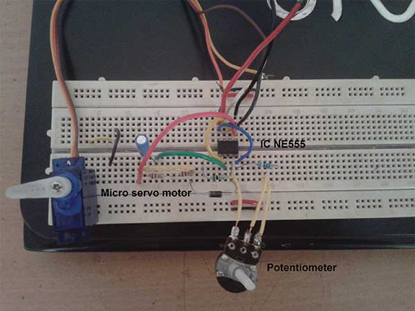
Fig. 1: Prototype of Arduino and Flex Sensor based Servo Motor Angle Controller
Circuit description
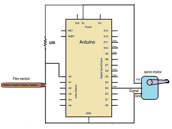
As shown in figure -:
1. Flex sensor is connected to analog input pin A0 in pull up configuration with pull-up resistor of 10 K
2. There are 3 wires of the servo motor. +V is connected to 5V and Gnd is connected to ground. The signal wire is connected to analog output pin 3.
3. Arduino board is connected to the computer with USB cable for programming as well as serial communication.
Circuit operation
• When flex sensor is straight its resistance is low. It gives corresponding analog voltage input to pin A0.
• The Arduino will convert this analog voltage into a digital value and depending upon it, it will generate PWM signal on analog output pin 3 to rotate the servo motor to desire angle.
• The actual angular position of the motor is read and displayed on serial monitor continuously after every second. The flex sensor bending value is also displayed on the serial monitor.
• As flex sensor is bent slowly its resistance will increase. So the analog voltage input at pin A0 will increase.
• The corresponding digital value will also increase and this will increase the width of output pulse at pin 3 to increase rotation angle of the servo motor.
• The servo motor rotation angle increases that is displayed on the serial monitor along with flex sensor bending value.
• When flex sensor is completely bent its resistance will be maximum and it gives max analog input. Its corresponding digital value is displayed on the serial monitor.
• The servo motor attains max angle that is 180o.
• Again when flex sensor bending is slowly released its resistance decreases – analog input decreases – analog output pulse decreases – motor angle decreases (motor rotates reversely).
• The flex sensor min and max bending values are calibrated and mapped to min and max servo motor rotation angle as 0o to 180o.
• So when flex sensor is at rest (not bent) the motor angle is 0o and when flex sensor is fully bent the motor angle is 180o.
Project Source Code
###
//Program to #include Servo.h // header file for servo library functions #define flex_sensor_ip A0 // flex sensor pin as A0 #define servo_motor_signal 3 // servo motor PWM ip signal as pin 3 Servo servo_motor; // create instance of servo class int servo_angle,actual_motor_angle;void setup() { servo_motor.attach(servo_motor_signal); // attach servo motor Serial.begin(9600); // initialize serial communication Servo_motor.write(90); // set motor angle to 90 deg }void loop() { int flex_sensor_value = analogRead(flex_sensor_ip);// read flex sensor // map its values in to servo motor angle values servo_angle = map(servo_angle,820,960,0,180);servo_motor.write(servo_angle); // rotate servo motor actual_motor_angle = servo_motor.read(); // read motor angle Serial.print(“flex sensor bending value = ”); Serial.println(flex_sensor_value); // display sensor value Serial.print(“motor angle = ”); Serial.print(actual_motor_angle); // and motor angle Serial.println(“ deg”); delay(1000); }###
Circuit Diagrams
| Circuit-Diagram-Arduino-Flex-Sensor-Based-Servo-Motor-Angle-Controller |  |
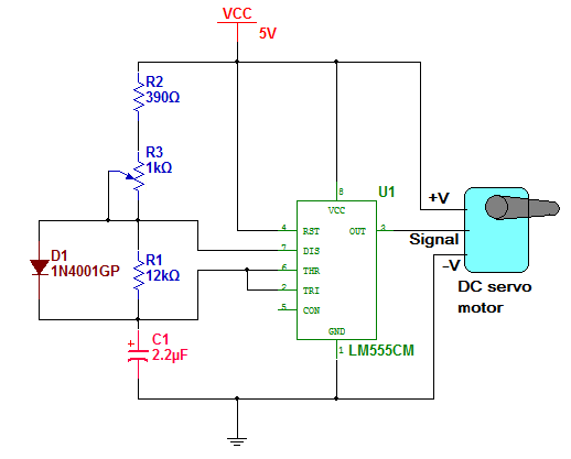
| Circuit-Diagram-555-IC-Based-Servo-Motor-Angle-Controller |  |
Project Video
Filed Under: Electronic Projects
Filed Under: Electronic Projects


Questions related to this article?
👉Ask and discuss on EDAboard.com and Electro-Tech-Online.com forums.
Tell Us What You Think!!
You must be logged in to post a comment.