Fig. 1: Prototype of Simple All-in-One Electronic Component Tester
Summary of the circuit-
1.It is not possible for the electronic beginners to buy a device which can test all the components as it is highly costly.
2.For all such people “All in one Tester” is a feasible solution.
3.This circuit is quite easy to make and also incurs low cost.
4.This device can test almost all kinds of components ranging from simple resistors to typical IC’s.
5.With the help of this device it is also easy to check the polarity of components, continuity testing and logic state as well as multi-vibrator activity.
Principle behind Circuit-
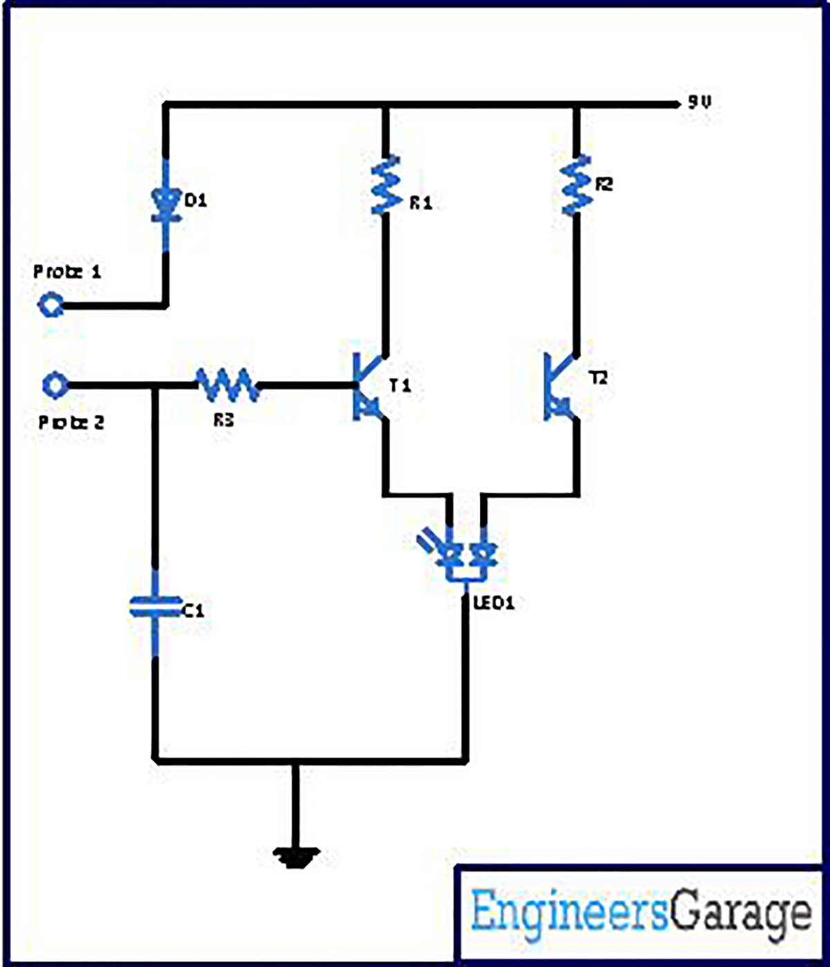
For the circuit is so much easy that the starter can also easily grab this circuit. This circuit is made up with the help of some passive components along with two transistors.T1 and T2 in the circuit work as a switch which is used to draw results, by driving the partial chunk of bi-chrome LED individually in sequence.
At the beginning, there is deficiency of forward bias voltage due to which transistor T1 does not conduct. In the same duration T2 starts conducting via resistor R1. Since T2 gets bias voltage from the power supply at the base, so the half chunk of bi-chrome LED (i.e. red) starts blinking.
Now when R3 provides positive voltage to the base of the transistor T1, it starts conducting and the rest half chunk (i.e. green) of LED starts blinking. Conduction of transistors T1 and T2 will be done one by one i.e. if T1 conducts, T2 will not and if T2 conducts, T1 will not.
Consequently, red and green LEDs will blink accordingly.
Transistor T1 conducts when the positive voltage through resistor R3 is given to base of transistor T1 and the green half of LED1 is lit up. In conduction of transistor T1, transistor T2 turns off and vice-versa.
The table given below shows the testing technique for a number of components along with the anticipated outcome.

Fig. 2: Image showing LED status for Component Detection
Components required building the circuit–
Resistor
R1 1.8K
R2 1.5K
R3 4.7K Capacitor
C1 1uF Diode
D1 1N4001 LED
LED1 Bi-colour LED Transistor
T1, T2 BC548
Power Supply 9V
Circuit Diagrams
Project Video
Filed Under: Circuit Design
Filed Under: Circuit Design


Questions related to this article?
👉Ask and discuss on EDAboard.com and Electro-Tech-Online.com forums.
Tell Us What You Think!!
You must be logged in to post a comment.