Engineers Garage

  • Electronic Projects & Tutorials
    • Electronic Projects
      • Arduino Projects
      • AVR
      • Raspberry pi
      • ESP8266
      • BeagleBone
      • 8051 Microcontroller
      • ARM
      • PIC Microcontroller
      • STM32
    • Tutorials
      • Audio Electronics
      • Battery Management
      • Brainwave
      • Electric Vehicles
      • EMI/EMC/RFI
      • Hardware Filters
      • IoT tutorials
      • Power Tutorials
      • Python
      • Sensors
      • USB
      • VHDL
    • Circuit Design
    • Project Videos
    • Components
  • Articles
    • Tech Articles
    • Insight
    • Invention Stories
    • How to
    • What Is
  • News
    • Electronic Product News
    • Business News
    • Company/Start-up News
    • DIY Reviews
    • Guest Post
  • Forums
    • EDABoard.com
    • Electro-Tech-Online
    • EG Forum Archive
  • DigiKey Store
    • Cables, Wires
    • Connectors, Interconnect
    • Discrete
    • Electromechanical
    • Embedded Computers
    • Enclosures, Hardware, Office
    • Integrated Circuits (ICs)
    • Isolators
    • LED/Optoelectronics
    • Passive
    • Power, Circuit Protection
    • Programmers
    • RF, Wireless
    • Semiconductors
    • Sensors, Transducers
    • Test Products
    • Tools
  • Learn
    • eBooks/Tech Tips
    • Design Guides
    • Learning Center
    • Tech Toolboxes
    • Webinars & Digital Events
  • Resources
    • Digital Issues
    • EE Training Days
    • LEAP Awards
    • Podcasts
    • Webinars / Digital Events
    • White Papers
    • Engineering Diversity & Inclusion
    • DesignFast
  • Guest Post Guidelines
  • Advertise
  • Subscribe

Water level sensor/detector interfacing with arduino uno

By EG Projects June 9, 2019

In this tutorial i am going to teach you how one can use arduino water level detector/sensor to detect presence of water. Interfacing water level sensor with arduino seems to be a piece of cake. Well its easy to interface and write code for arduino water level detector, but in the long run it might pop up some problems. Like sensitivity issues etc. In complex applications like measuring the quantity of liquid in a tank more sensor resolution is required and complexity of physical quantities like volume of water in tank, flow rate of water increases the arduino program complexity. Only very few programmers were able to use arduino water level sensor in complex applications and develop code for the application considering all the physical quantities.     

I will try to discus all the physical quantities and under what circumstances they are needed to be taken under consideration. Lets begin which the introduction of the arduino water level sensor and how it works?

How arduino water/rain/moisture level sensor/detector works?

Arduino water level sensor comes in many sizes and with many names. You can find them on internet under names as arduino water sensor, arduino moisture sensor, arduino rain sensor, arduino leakage sensor etc. But universally they all are composed of same electronic equipment and works on same principle.  
Different types of arduino water level sensors

Arduino water/rain/moisture level sensors/detectors various types/kinds

In the above picture you can see different types of water sensors available in market. Most popular is the last one with two legs and a small circuit behind it.  

All the sensors are analog. Means they provide and analog output. Analog output is in range from 0 to 5 volts. We need to read this analog voltage using ADC(analog to digital converter) and convert it to equivalent digital value fr future computations. 

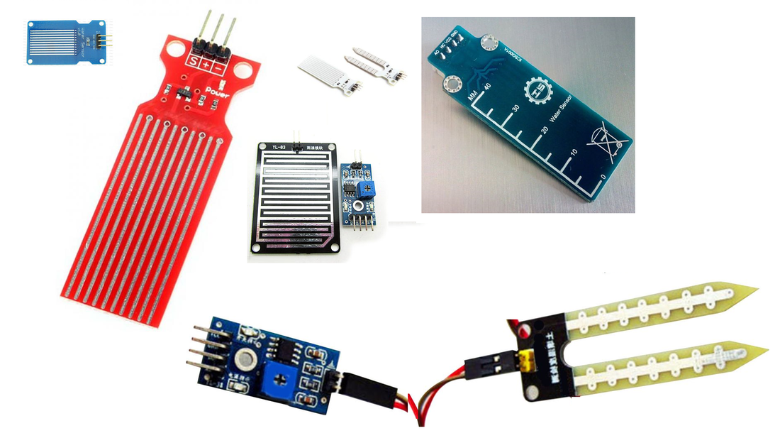
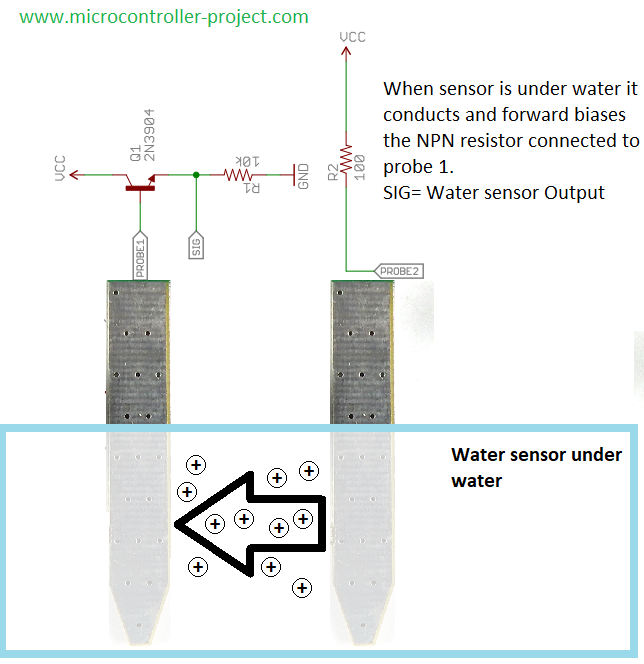
​All water sensors have two legs. Some have multiple stripes. Each leg or strip is plated with a conducting material often copper. Both legs of water level sensor act as a variable resistor. To one leg we supply +voltage and to other we make ground. When both the legs are dipped in water an electric path is created between the two legs and sensor start conducting current. The value of conductance/current depends on the ratio or level of water. In the below diagram water sensor circuit and how it works is broadly highlighted. 

Note: When arduino water level sensor is continuously exposed to water. Its copper starts to peer off from legs and the sensor starts decomposing. Its the biggest draw back of water detector. The life time of sensor can be increased by plating its copper part or legs with gold(not original gold; process name is gold platting). I advice you to purchase the sensor whose legs are protected from this decomposing phenomena. I used water/soil moisture sensors in big plant pots and the sensors starts giving malware error prone readings after 1 week 🙁 

Arduino water sensor circuit working principle

Arduino water sensor circuit working principle

Arduino soil moisture level sensor which comes with an extra module or circuit contains a comparator along with a variable resistor/potentiometer. This module can output a digital and analog value. During digital output user set a threshold value for input voltage. When the input value rises above the threshold comparator sets the digital output high. Digital output is useful in case of alarms to check when the threshold level of water is crossed. Analog output for this circuit works on the same principle explained above. Equivalent circuit of the board is given below. 

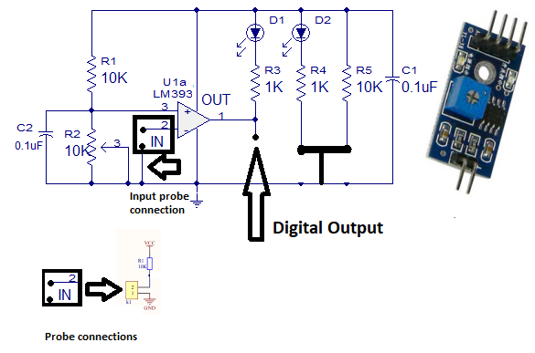
Its little hard for newbies to understand whats going on in the circuit and how it is producing the result. I suggest to skip it and move on 😀 

Arduino soil moisture sensor comparator circuit connections and working

Arduino soil moisture sensor comparator circuit connections and working

Where can arduino water detector can be used?

  • Arduino water sensor can be used to check the leakage of water or viscous substance from pipes.
  • Water detector can be used to check spil of water from tank.
  • Water sensor can measure the salinity or moisture water content in soil.
  • Flood and rain situation can be monitored.
  • Quantity or level of water in tank can easily be monitored using arduino water level sensor.
  • Water sensor can be utilized to monitor and water the garden. 

Interfacing water level sensor with arduino uno

Recall we can interface water detector with arduino in digital as well as analog form. I am going to write arduino code for both type of interface. Lets start with the analog interface. Arduino will read the analog output of the water sensor and display it on serial monitor of arduino. I expect that you people know about arduino serial monitor and its working. Also i expect from you that you are familiar with the arduino ADC reading analog voltages and ADC quantization etc. 

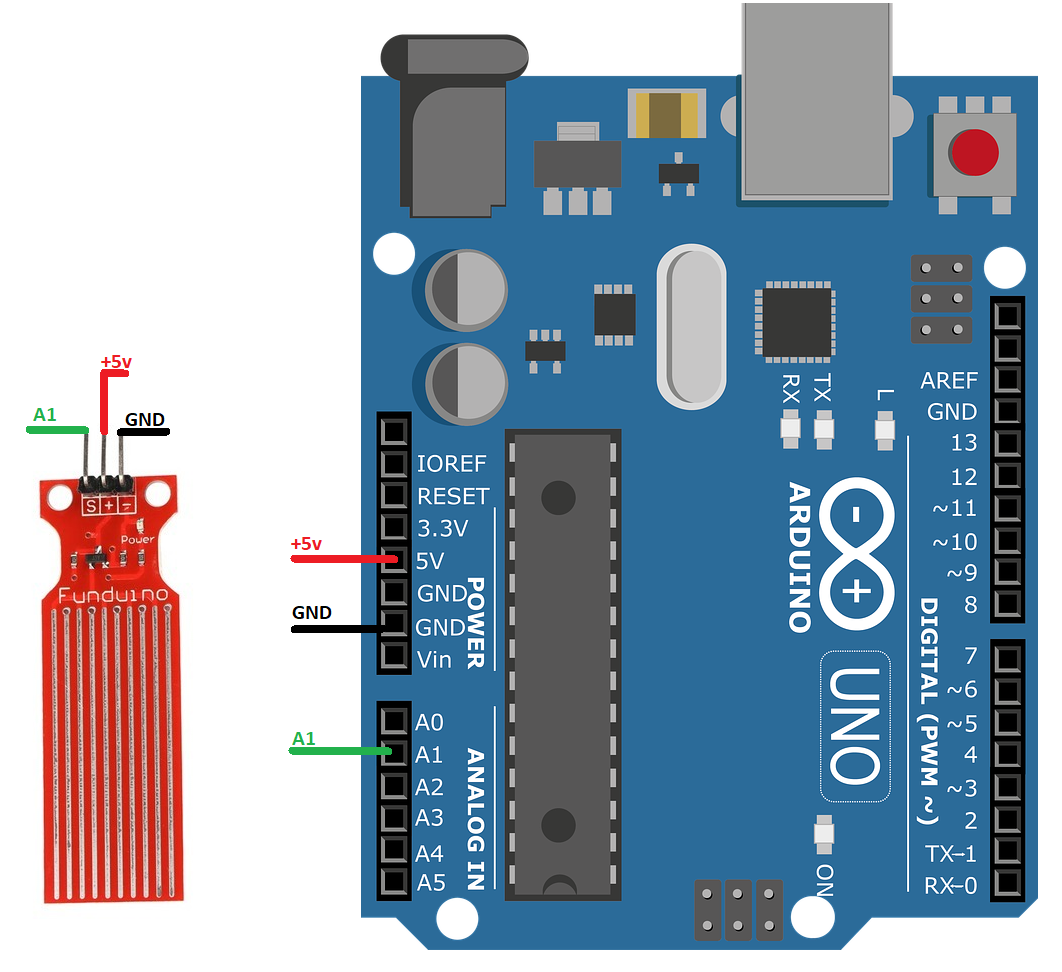
I am going to connect the analog output of arduino water sensor to arduino analog channel 1. The code of the project is simple. In setup() function of arduino code serial monitor of arduino is initialized at 9600 bps. The instruction Serial.begin(9600) is starting the serial monitor. In the loop function i am reading the analog channel 1 of ADC. The instruction int sensor=analogRead(A1) reads the analog channel and stores the analog value in variable sensor. Next instruction Serial.println(sensor) prints the water sensor analog reading on serial monitor of arduino. 

Arduino water sensor as analog input

Circuit diagram of Arduino uno with water level sensor is given below. The circuit is for the above code Arduino and water detector as analog. 
Arduino water sensor analog output

Arduino water sensor analog output

In analog water detector circuit i used the sensor with multiple copper stripes on it. Note their is no extra circuit only bare sensor with some resistors and a single transistor on it. 

Now lets start the digital part. Water sensor will output a high 5 volt signal as output on its D0 pin when the water touches the sensors legs. The threshold also plays a vital role here. If the quantity of water increase the threshold level(explained above) only then the D0 pin goes high. Arduino digital pin 3 is used to check the status of water detector D0 pin. If its high then arduino will buzz an alarm which is connected to pin 8 of ardunio. 

Same like analog sensor code arduino water detector digital code is simple, straight forward and easy to understand. First the Arduino pins are defined by using define macro.   
#define Danger 3 
#define ALARM 8

Arduino pin 3 is named as Danger and 8 as ALARM.  In the setup() function both the pins are declared OUTPUT. The statements   
pinMode(Danger, INPUT)

pinMode(ALARM, OUTPUT)

declares the pins as output

In the loop() function i am reading the Danger pin. The if statement  if( digitalRead(Danger) == LOW) is reading the status of Danger pin. If found high i switch ON the ALARM. If found low i switch OFF the ALARM. The statement digitalWrite(ALARM, LOW/HIGH) switches the alarm ON and OFF.  

Arduino water sensor as digital input

Circuit diagram of the above code is below. 1 k ohm resistor is used with the buzzer in series to limit the current going in the buzzer. Each component can be powered through arduino digital 5 volt output.
Picture

Arduino water sensor as digital input to arduino

Advance project on how to measure quantity of water in a tank using arduino is prototype in the next project. Different techniques are discussed about how we can measure the quantity of water in tank using arduino water sensor. Tutorial link is below.  

How to measure quantity of water in tank with arduino uno?

Project codes


Filed Under: Arduino Projects, Microcontroller Projects


Next Article

← Previous Article
Next Article →

Questions related to this article?
👉Ask and discuss on Electro-Tech-Online.com and EDAboard.com forums.


Tell Us What You Think!! Cancel reply

You must be logged in to post a comment.

EE TECH TOOLBOX

“ee
Tech Toolbox: Internet of Things
Explore practical strategies for minimizing attack surfaces, managing memory efficiently, and securing firmware. Download now to ensure your IoT implementations remain secure, efficient, and future-ready.

EE Learning Center

EE Learning Center
“engineers
EXPAND YOUR KNOWLEDGE AND STAY CONNECTED
Get the latest info on technologies, tools and strategies for EE professionals.

HAVE A QUESTION?

Have a technical question about an article or other engineering questions? Check out our engineering forums EDABoard.com and Electro-Tech-Online.com where you can get those questions asked and answered by your peers!


RSS EDABOARD.com Discussions

  • Multiple DC/DC converters and a single input source
  • Xiaomi Mijia 1C Robot problem of going backwards while working
  • Will this TL084C based current clamp circuit work?
  • ADS optimization cockpit window does not open
  • Voltage mode pushpull is a nonsense SMPS?

RSS Electro-Tech-Online.com Discussions

  • Parts required for a personal project
  • Curved lines in PCB design
  • Wideband matching an electrically short bowtie antenna; 50 ohm, 434 MHz
  • using a RTC in SF basic
  • PIC KIT 3 not able to program dsPIC

Featured – RPi Python Programming (27 Part)

  • RPi Python Programming 21: The SIM900A AT commands
  • RPi Python Programming 22: Calls & SMS using a SIM900A GSM-GPRS modem
  • RPi Python Programming 23: Interfacing a NEO-6MV2 GPS module with Raspberry Pi
  • RPi Python Programming 24: I2C explained
  • RPi Python Programming 25 – Synchronous serial communication in Raspberry Pi using I2C protocol
  • RPi Python Programming 26 – Interfacing ADXL345 accelerometer sensor with Raspberry Pi

Recent Articles

  • AC-DC power supply extends voltage range to 800 V DC
  • Infineon’s inductive sensor integrates coil system driver, signal conditioning circuits and DSP
  • Arm Cortex-M23 MCU delivers 87.5 µA/MHz active mode
  • STMicroelectronics releases automotive amplifiers with in-play open-load detection
  • Convection-cooled power controller integrates EtherCat connectivity

EE ENGINEERING TRAINING DAYS

engineering

Submit a Guest Post

submit a guest post
Engineers Garage
  • Analog IC TIps
  • Connector Tips
  • Battery Power Tips
  • DesignFast
  • EDABoard Forums
  • EE World Online
  • Electro-Tech-Online Forums
  • EV Engineering
  • Microcontroller Tips
  • Power Electronic Tips
  • Sensor Tips
  • Test and Measurement Tips
  • 5G Technology World
  • Subscribe to our newsletter
  • About Us
  • Contact Us
  • Advertise

Copyright © 2025 WTWH Media LLC. All Rights Reserved. The material on this site may not be reproduced, distributed, transmitted, cached or otherwise used, except with the prior written permission of WTWH Media
Privacy Policy

Search Engineers Garage

  • Electronic Projects & Tutorials
    • Electronic Projects
      • Arduino Projects
      • AVR
      • Raspberry pi
      • ESP8266
      • BeagleBone
      • 8051 Microcontroller
      • ARM
      • PIC Microcontroller
      • STM32
    • Tutorials
      • Audio Electronics
      • Battery Management
      • Brainwave
      • Electric Vehicles
      • EMI/EMC/RFI
      • Hardware Filters
      • IoT tutorials
      • Power Tutorials
      • Python
      • Sensors
      • USB
      • VHDL
    • Circuit Design
    • Project Videos
    • Components
  • Articles
    • Tech Articles
    • Insight
    • Invention Stories
    • How to
    • What Is
  • News
    • Electronic Product News
    • Business News
    • Company/Start-up News
    • DIY Reviews
    • Guest Post
  • Forums
    • EDABoard.com
    • Electro-Tech-Online
    • EG Forum Archive
  • DigiKey Store
    • Cables, Wires
    • Connectors, Interconnect
    • Discrete
    • Electromechanical
    • Embedded Computers
    • Enclosures, Hardware, Office
    • Integrated Circuits (ICs)
    • Isolators
    • LED/Optoelectronics
    • Passive
    • Power, Circuit Protection
    • Programmers
    • RF, Wireless
    • Semiconductors
    • Sensors, Transducers
    • Test Products
    • Tools
  • Learn
    • eBooks/Tech Tips
    • Design Guides
    • Learning Center
    • Tech Toolboxes
    • Webinars & Digital Events
  • Resources
    • Digital Issues
    • EE Training Days
    • LEAP Awards
    • Podcasts
    • Webinars / Digital Events
    • White Papers
    • Engineering Diversity & Inclusion
    • DesignFast
  • Guest Post Guidelines
  • Advertise
  • Subscribe